Anti-sticking and diagnostic strategy for exhaust system valves

An exhaust system, waste gate valve technology, applied in electrical control, combustion engine, machine/engine, etc., to solve problems such as turbocharger or engine failure

Inactive Publication Date: 2014-07-23
CATERPILLAR INC
View PDF5 Cites 10 Cited by
  • Summary
  • Abstract
  • Description
  • Claims
  • Application Information

AI Technical Summary

Problems solved by technology

While not necessarily true for all valves, such as those controlling exhaust gas recirculation...

Method used


Image

  • Anti-sticking and diagnostic strategy for exhaust system valves
  • Anti-sticking and diagnostic strategy for exhaust system valves

Examples


Embodiment Construction

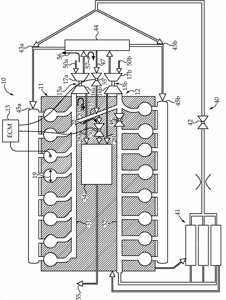
[0008] see figure 1 , shows an exemplary engine system 10 according to the present invention. Engine system 10 includes an electronically controlled engine 11 fluidly connected to an exhaust system 12 . In the illustrated embodiment, the engine 11 is a sixteen cylinder large bore compression ignition engine, the operation of which is controlled by an electronic controller 13 . One aspect of engine control is the operation of electronically controlled fuel injectors (not shown) associated with each of the individual large bore cylinders 19, which may have a bore size in excess of 140 millimeters. Also, in the illustrated embodiment, the electronically controlled engine 11 has a V-configuration with two separate banks of eight engine cylinders each. Thus, the engine 11 has a first exhaust manifold 31 and a second exhaust manifold 32, which may be considered part of the exhaust system 12, which exhausts The tailpipe 35 terminates. Although not required, equalization duct 33 m...


PUM


Abstract

An engine system (10) includes an exhaust system (12) fluidly connected to an electronically controlled engine (11). Exhaust from the engine may travel a first pathway (20) through a turbine (16) of a turbocharger (15), or a second pathway (22) that bypasses the turbine (16). An electronically controlled wastegate vale is biased to close the second pathway (22). An electronic controller (13) is in communication with the electronically controlled engine (11) and the electronically controlled wastegate valve. The electronic controller (13) is configured to execute a wastegate diagnostic algorithm to detect a stuck closed default condition of the electronically controlled wastegate valve, and derate the engine in response to detection of a stuck closed fault condition.

Description

technical field [0001] The present invention relates generally to engine systems having electronically controlled valves located in exhaust systems, and more particularly to an active diagnostic method for detecting and avoiding a stuck closed valve condition. Background technique [0002] Today's engine systems are typically equipped with one or more turbochargers, an exhaust gas recirculation system, and electronically controlled valves in the exhaust system that control the compressor bypass, turbine bypass , mass flow rate of recirculated exhaust gas, and other known control characteristics. Exhaust passage away from the turbine is typically controlled by a device known in the art as a wastegate valve. For example, when boost pressure approaches some predetermined maximum or there is a risk of turbo overspeed, the wastegate valve can be opened to direct exhaust gas from the exhaust manifold towards the tailpipe without transferring energy to the Turbocharger. Due to v...

Claims


Application Information

Patent Timeline
IPC IPC(8): F02B37/18F02B37/12F02B39/00F02D41/22
CPCF02B37/001F02B37/007F02B37/18F02B39/16Y02T10/12
Inventor A·C·卢福特D·斯特勒特克R·桑卡尔T·E·巴恩斯G·L·阿姆斯特朗
Owner CATERPILLAR INC
Why Eureka
Try Eureka