
Automatic polishing machine for flange surface of rotary body

A technology of automatic polishing and rotating body, applied in the field of polishing machines, can solve the problems of flange surface effect, reduce efficiency and quality, increase equipment complexity and operation difficulty, simplify the complexity and operation difficulty, and reduce coordination operations. time, improved efficiency and quality

Active Publication Date: 2014-07-30
CHINA NUCLEAR POWER TECH RES INST CO LTD +2
View PDF6 Cites 9 Cited by
  • Summary
  • Abstract
  • Description
  • Claims
  • Application Information

AI Technical Summary

Problems solved by technology

[0005] However, since the grinding machine and the polishing machine are two independent devices separated from each other, and the large-scale rotary body is a bulky and heavy workpiece, the process of processing the flange surface of the large-scale rotary body will increase the distance between the equipment. Cooperate with the operation time, increase the risk of equipment cross-operation, and increase the complexity and operation difficulty of equipment, thereby reducing efficiency and quality
Especially when the large rotating body is used in radioactive occasions, the above defects are more obvious
[0006] Furthermore, the detection of the flange surface of the large-scale rotary body after grinding and polishing is based on manual visual inspection, so the results of the processed flange surface of the large-scale rotary body are easily affected by the subjective judgment of the operator

Method used


Image

  • Automatic polishing machine for flange surface of rotary body
  • Automatic polishing machine for flange surface of rotary body
  • Automatic polishing machine for flange surface of rotary body

Examples


Embodiment Construction

[0036] Embodiments of the present invention will now be described with reference to the drawings, in which like reference numerals represent like elements.

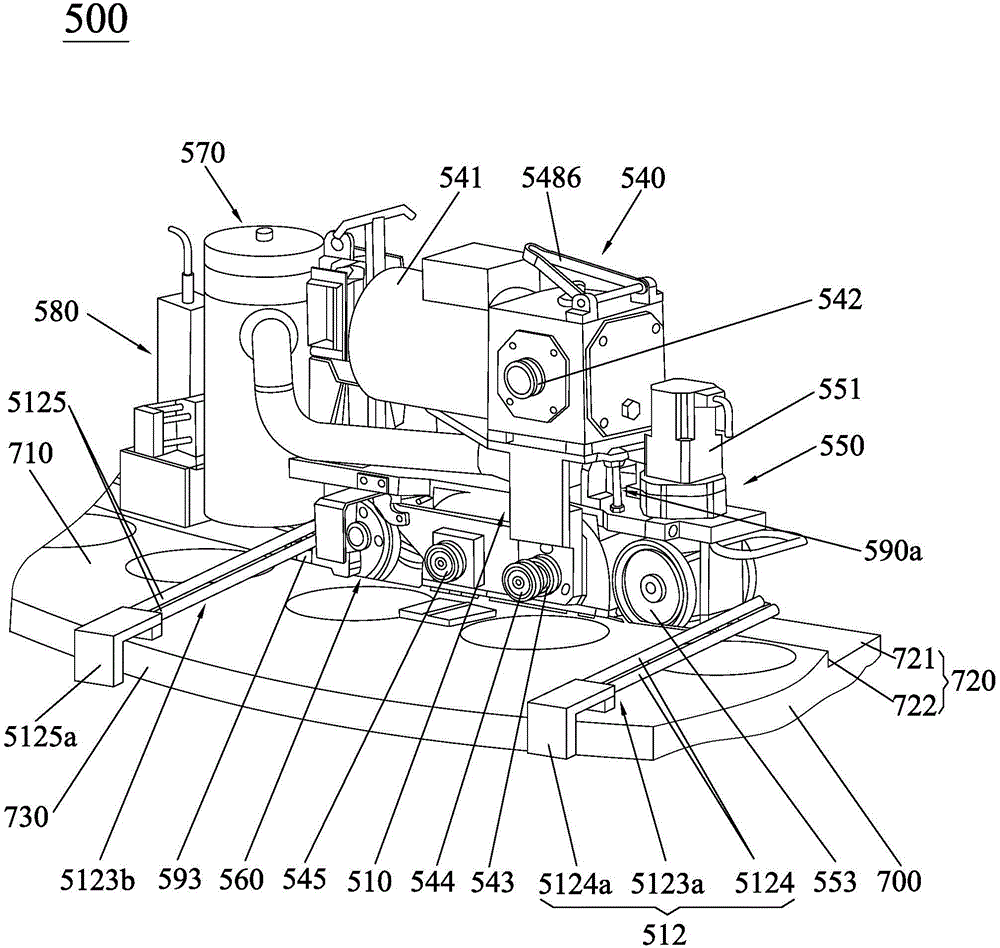
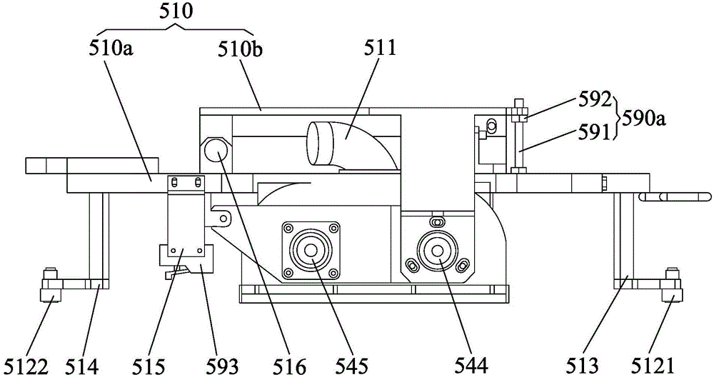
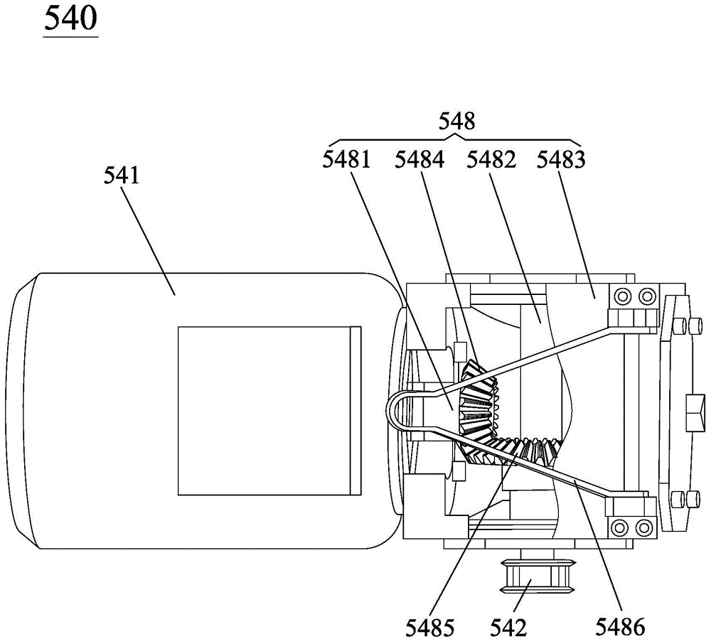
[0037] see figure 1 and figure 2 ,as well as Figure 6 and Figure 7 , the rotary body flange surface automatic polishing machine 500 of the present invention is electrically connected with the controller, and the flange surface of the large rotary body 700 (not noted in the figure) is polished and polished, so that the flange surface of the rotary body 700 and the large-scale rotary body 700 has a guide track 720 around the center line of the large-scale rotary body 700. Specifically, the guide track 720 includes a support surface 721 and a guide side surface 722. The support surface 721 is staggered below the top surface 710 of the large-scale rotary body 700, of course, it can also be located under the top surface 710 of the large-scale rotary body 700, so that the support surface 721 and the top surface 710 are no...


PUM


Abstract

The invention discloses an automatic polishing machine for a flange surface of a rotary body, and is suitable for carrying out grinding and polishing treatment on the flange surface of the large rotary body. The large rotary body is provided with a guide rail which is arranged around the rotary center line of the large rotary body. The automatic polishing machine for the flange surface of the large rotary body comprises a machine frame, a grinding assembly, a polishing assembly, a grinding and polishing driving assembly, a travel driving assembly and a travel driven assembly, wherein the grinding assembly and the polishing assembly are respectively arranged on the machine frame and are respectively opposite to the flange surface, the grinding and polishing driving assembly is arranged on the machine frame and is used for providing the driving power for the grinding assembly and the polishing assembly, the travel driving assembly and the travel driven assembly are sequentially arranged on the machine frame along the grinding assembly and the polishing assembly, and are respectively supported between the machine frame and the guide rail, and the travel driving assembly drives the machine frame to move along the guide rail, so as to improve the grinding and polishing efficiency and the grinding and polishing quality.

Description

technical field [0001] The invention relates to a polishing machine, in particular to an automatic flange surface polishing machine of a rotary body capable of grinding and polishing the flange surface of a large rotary body. Background technique [0002] As we all know, the parts used in mechanical equipment have the requirements of machining accuracy and assembly accuracy. In order to meet the various accuracy requirements of the workpiece, the usual practice is to use cutting tools with different precision to perform multiple cutting processes on the workpiece. To achieve the required accuracy requirements; or, with the help of a combination of a grinding machine and a polishing machine, the workpiece is ground and polished to achieve the required accuracy. Since the combination of grinding and polishing can better ensure the accuracy requirements of the workpiece, the process of processing workpieces with the help of grinding machines and polishing machines is more favor...

Claims


Application Information

Patent Timeline
Patent Type & Authority Applications(China)
IPC IPC(8): B24B5/04B24B29/04B24B49/12B24B41/04
CPCB24B5/36B24B29/005B24B29/02B24B29/04B24B41/00B24B41/04B24B49/00B24B49/12B24B55/06
Inventor 刘青松陈嘉杰余冰朱磊张涛孟海军李晓程鹏董亚超葛月胜詹雨华李志
Owner CHINA NUCLEAR POWER TECH RES INST CO LTD
Learn More