
clip gun

A code clamping gun and code clamping technology, applied in the field of code clamping guns, can solve the problems of shortening the service life of the air valve assembly, high maintenance cost, short service life of the air valve assembly, etc. Convenient, solve the effect of easy breakage

Active Publication Date: 2016-02-03
闫强
View PDF6 Cites 0 Cited by
  • Summary
  • Abstract
  • Description
  • Claims
  • Application Information

AI Technical Summary

Problems solved by technology

As we all know, O-rings are generally made of rubber materials. Due to the frequent top pressure of the valve core, one end will fail after being used for a while. Once it fails, the air valve will leak and cause the clamping gun to malfunction. For this reason, it is necessary to replace the air valve assembly as a whole. At present, the price of a general air valve assembly is 120 yuan / piece, and the normal service life is two months. For ordinary users, the maintenance cost is too high. High, this is also one of the shortcomings of the existing clip gun
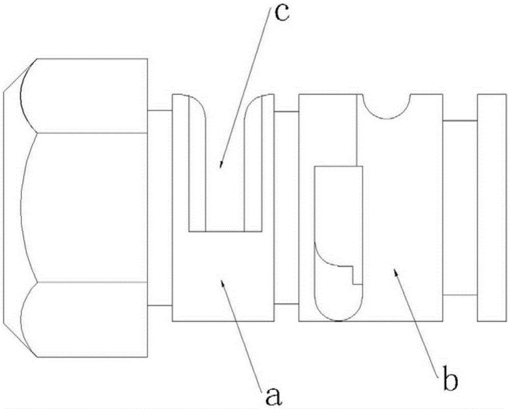
In addition, since the sides of the front chamber a and the rear chamber b need to be provided with arc-shaped slots c, the structure is as follows figure 1 As shown, for ventilation, the arc-shaped slot c generally needs to occupy 3 / 4 of the circumference of the valve sleeve, and only the remaining 1 / 4 is used as a connection support. Due to the offset of the center of gravity, the torque of this design is relatively large. In the process of use, it is easy to cause the breakage of the connecting support part, further shortening the life of the air valve assembly
For this reason, those skilled in the art try to add a support column in the middle of the arc-shaped slot hole. However, due to the increase of the support column, the strength of the valve sleeve can be increased theoretically, but the intake and exhaust volume of the slot hole is reduced. It takes a long time to shoot the second shot after each shot is clamped, which greatly reduces the frequency of clamping. Obviously this solution is not feasible; for this reason, it is also proposed to use multiple The air holes arranged in the circumferential direction can be replaced, but because the side of the valve sleeve has to reserve a space for setting the positioning hole for the installation of the positioning pin, it cannot be realized because of the insufficient space on the surface of the valve sleeve. Therefore, although the air valve of the clip gun is always The problem of short service life and high maintenance cost has existed for a long time, but it has not been solved in the end
[0005] 2. The design of the control valve assembly is unreasonable
The current control valve assembly is positioned by the pin shaft, the spool of the control valve assembly directly contacts the trigger, and is subjected to the top pressure of the trigger for a long time, which will inevitably cause problems such as loosening

Method used


Image

  • clip gun
  • clip gun
  • clip gun

Examples


Embodiment Construction

[0031] The specific embodiments of the present invention will be described in further detail below in conjunction with specific examples.

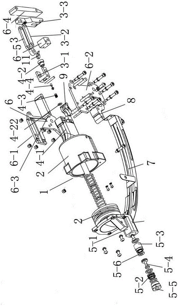
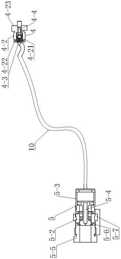
[0032] Such as Figure 2-Figure 5 As shown, a clamping gun of the present invention includes a gun body 1 and a cylinder 2 arranged on it, a connecting rod mechanism 3 connected to the cylinder piston rod, a control valve assembly 4 and an air valve assembly 5, and the gun body 1 is provided with The L-shaped guide groove 6 corresponding to the link mechanism 3 and the clamping code groove 7 loaded with the clamping code, the code outlet of the clamping groove 7 is connected with the L-shaped guide groove 6, and the end of the L-shaped guide groove 6 is provided with a clamping dock 8 , the control valve assembly 4 is connected with a trigger 9 . The L-shaped guide groove 6 includes L-shaped left and right side panels 6-1, 6-2 and a top panel 6-3, a guide panel 6-4 and a guide block 6 arranged between the left and right side panels. -5, ...


PUM


Abstract

The invention discloses a clinching gun, which comprises a gun body, an air cylinder, a link mechanism, a control valve assembly and an air valve assembly, the air cylinder, the link mechanism, the control valve assembly and the air valve assembly are arranged on the gun body, the link mechanism is connected with the piston rod of the air cylinder, the gun body is provided with an L-shaped guide way corresponding to the link mechanism and a clinching clip channel for loading clinching clips, and an air passage is connected between the control valve assembly and the air valve assembly. The clinching gun is characterized in that: the air valve assembly comprises an air valve cylinder sleeve, a spacer bush and a first valve sleeve, the air valve cylinder sleeve is connected with the air cylinder, the spacer bush and the first valve sleeve are sequentially arranged in the air valve cylinder sleeve, an end cover is movably mounted on the end of the air valve cylinder sleeve, and the periphery of the spacer bush is provided with a plurality of first air holes; the periphery of the first valve sleeve is provided with a plurality of second air holes; the control valve assembly comprises a control valve cylinder sleeve and a second valve sleeve, the control valve cylinder sleeve is connected with the air cylinder, the second valve sleeve is screwed in the control valve cylinder sleeve, a spring and a second spool are movably arranged in the second valve sleeve, and the other end of the second spool runs through the second valve sleeve and presses a trigger lever on a trigger. The clinching gun has a simple structure, is convenient to assemble and use and has a long service life.

Description

technical field [0001] The invention relates to the technical field of clamping guns. Background technique [0002] Clamp gun, also known as buckle gun, is mainly suitable for the connection between independent pocket springs and the fastening of mattresses, sofas, car seat cushion springs and frames, etc., which can effectively improve work efficiency. Structurally, it is mainly composed of air valve assembly, cylinder, clamping groove, side plates on both sides, top plate, control valve, trigger and clamping terminal. The air valve assembly is connected to the intake end of the cylinder, and the side plates on both sides are connected to the The end of the cylinder is connected with the top plate to form a gun body structure with a guide groove and a connecting rod inside. The clamping dock is arranged at the end of the guide groove, and the code output end of the clamp groove is connected to the guide groove. The valve and trigger drive the cylinder to move, thereby driv...

Claims


Application Information

Patent Timeline
Patent Type & Authority Patents(China)
IPC IPC(8): B25B27/00F15B13/02
CPCB25B27/00F15B13/0405
Inventor 闫强
Owner 闫强
Learn More