Mechanical automatic clamping grip

An automatic clamping and mechanical technology, applied in the direction of manipulators, program-controlled manipulators, chucks, etc., can solve the problems of high risk factor, low production efficiency, high production cost, etc.

Active Publication Date: 2014-07-30
ANHUI HISEED ROBOT CO LTD
View PDF6 Cites 9 Cited by
  • Summary
  • Abstract
  • Description
  • Claims
  • Application Information

AI Technical Summary

Problems solved by technology

However, due to technical limitations, in today's field of workpiece handling, such as I-shaped wheels and wire reels, which are large at both ends and small in the middle, and have a large mass, most of them are carried out by manual handling, and the labor cost invested in this way is relatively large. , low production efficiency
[0003] Most of the existing mechanical grippers are manually clamped and grasped, and manually separated and put down. The risk factor of manual operation is extremely high, the production cost is high, and the production efficiency is low; The grippers that can realize automatic clamping and automatic release need to use the drive motor or drive cylinder

Method used


Image

  • Mechanical automatic clamping grip
  • Mechanical automatic clamping grip
  • Mechanical automatic clamping grip

Examples


Embodiment Construction

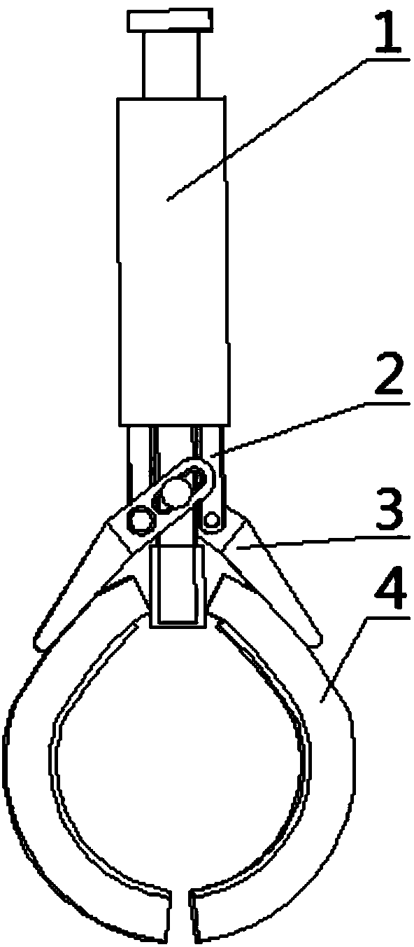
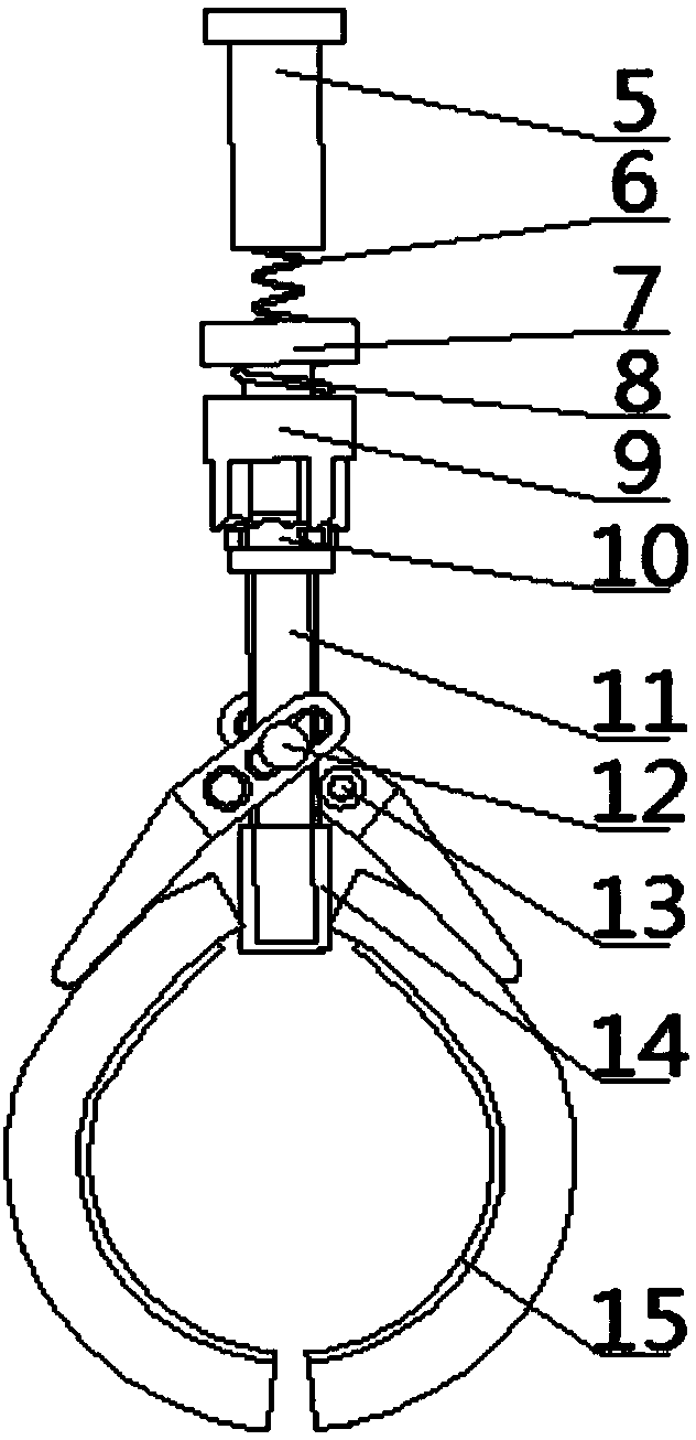
[0021] Such as figure 1 , figure 2 As shown, the mechanical automatic clamping gripper provided by the present invention includes a cage 1, a sliding cylinder 2, a claw 3, a snap ring 4, a connecting rod 5, a telescopic spring 6, a copper sleeve 7, a compression spring 8, and a sliding claw Rotary cylinder 9, sliding claw sleeve 10, mandrel 11 and copper top sleeve 14.

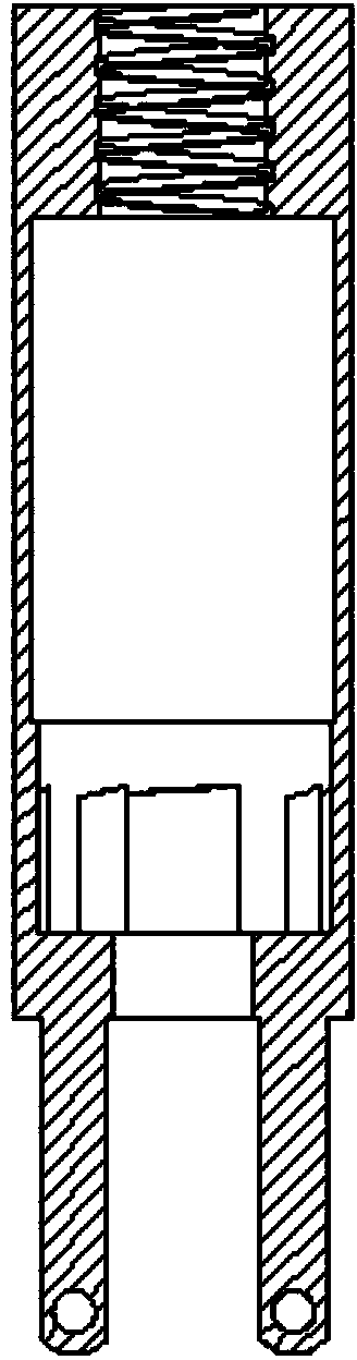
[0022] Such as figure 1 , image 3 , Figure 4 As shown, the cage 1 is a stepped cavity with threaded holes on the top; the outer wall of the slider 2 has four bosses, the bosses and grooves are arranged in a staggered manner, and each boss has two slide grooves. There are two extending arms at the lower end of the cylinder 2, and a threaded hole is respectively provided at the lower part of the two extending arms; the sliding cylinder 2 is fixedly connected in the cage 1.

[0023] Such as figure 1 As shown, the connecting rod 5 is threaded and connected to the threaded hole of the cage 1 of the cage ...


PUM


Abstract

The invention discloses a mechanical automatic clamping grip, and belongs to the technical field of mechanical automatic carrying. The automatic clamping grip comprises a retainer, a sliding drum, a paw, a snap ring, a connecting rod, a retractable spring, a copper sleeve, a compression spring, a sliding claw rotating drum, a sliding claw sleeve, a core shaft and a copper top sleeve, wherein the lower end of the connecting rod is connected with the retainer; the copper sleeve is fixedly connected with the upper end of the core shaft; the core shaft is sleeved with the compression spring, the sliding claw rotating drum, the sliding claw sleeve and the sliding sleeve from top to bottom; the paw is linked to the extending arm of the sliding drum and the lower end of the core shaft respectively through a bolt and a rotating hinge pin; the snap ring is fixedly connected with the paw 3; a rubber pad is arranged on the inner surface of the snap ring; the bottom of the core shaft is fixedly sleeved with the copper top sleeve. The automatic clamping grip provided by the invention can realize the carrying of automatically grasping and laying down workpieces, and is particularly suitable for workpieces, such as I-shaped steel, wire coils, and the like, which have large both ends and a small middle part, have larger quality and are difficult to achieve the automatic grasping and laying down.

Description

Technical field: [0001] The invention belongs to the technical field of mechanical automatic handling, and in particular relates to a mechanical automatic clamping gripper, which is suitable for various handling operations of automatic grabbing and automatic delivery, such as the handling of I-shaped wheels and wire reels. . Background technique: [0002] With the continuous development of science and technology, more and more fields are replacing manual production with mechanical production. However, due to technical limitations, in today's field of workpiece handling, such as I-shaped wheels and wire reels, which are large at both ends and small in the middle, and have a large mass, most of them are carried out by manual handling, and the labor cost invested in this way is relatively large. , Low production efficiency. [0003] Most of the existing mechanical grippers are manually clamped and grasped, and manually separated and put down. The risk factor of manual operati...

Claims


Application Information

Patent Timeline
Patent Type & Authority Applications(China)
IPC IPC(8): B25J9/00B25J15/08
Inventor 张良安谭玉良解安东王鹏万俊高鲁文柏家峰
Owner ANHUI HISEED ROBOT CO LTD
Why Eureka
Try Eureka