Rotation type mold locking mechanism

A rotary and clamping technology, applied in the field of rotary clamping mechanism, can solve the problems of large noise and vibration, affecting the performance and service life of the machine, and achieve the effect of reducing power transmission and working stably and reliably

Active Publication Date: 2014-07-30
广州西力机械有限公司
View PDF6 Cites 6 Cited by
  • Summary
  • Abstract
  • Description
  • Claims
  • Application Information

AI Technical Summary

Problems solved by technology

This changing intermittent force produces a reaction force on the formwork, which is decomposed into a resistance in the circumferential direction of the formwork and a force in the up and down direction, which causes greater noise and vibration during the high-speed operation of the machine, which seriously affects the machine. performance and service life

Method used


Image

  • Rotation type mold locking mechanism
  • Rotation type mold locking mechanism
  • Rotation type mold locking mechanism

Examples


Embodiment Construction

[0025] The idea, specific structure and technical effects of the present invention will be clearly and completely described below in conjunction with the embodiments and accompanying drawings, so as to fully understand the purpose, features and effects of the present invention. Apparently, the described embodiments are only some of the embodiments of the present invention, rather than all of them. Based on the embodiments of the present invention, other embodiments obtained by those skilled in the art without creative efforts belong to The protection scope of the present invention. In addition, all the connection / connection relationships mentioned in this article do not refer to the direct connection of components, but mean that a better connection structure can be formed by adding or reducing connection accessories according to specific implementation conditions.

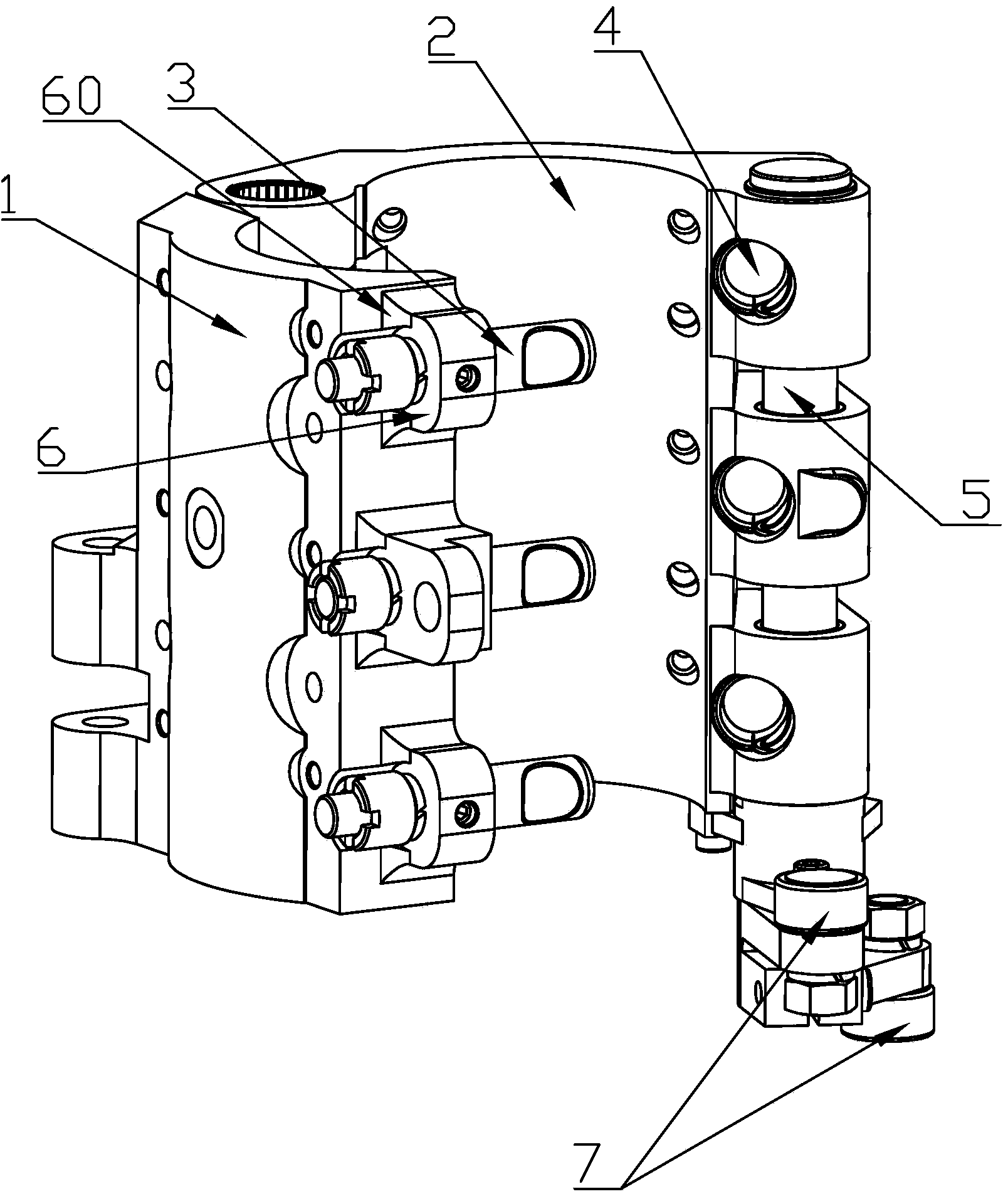
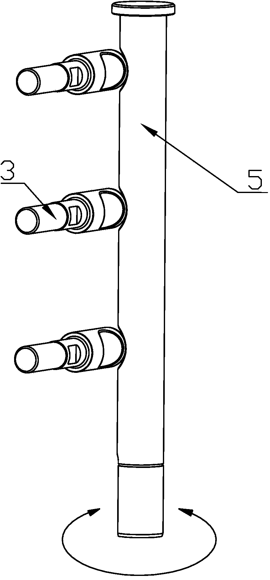
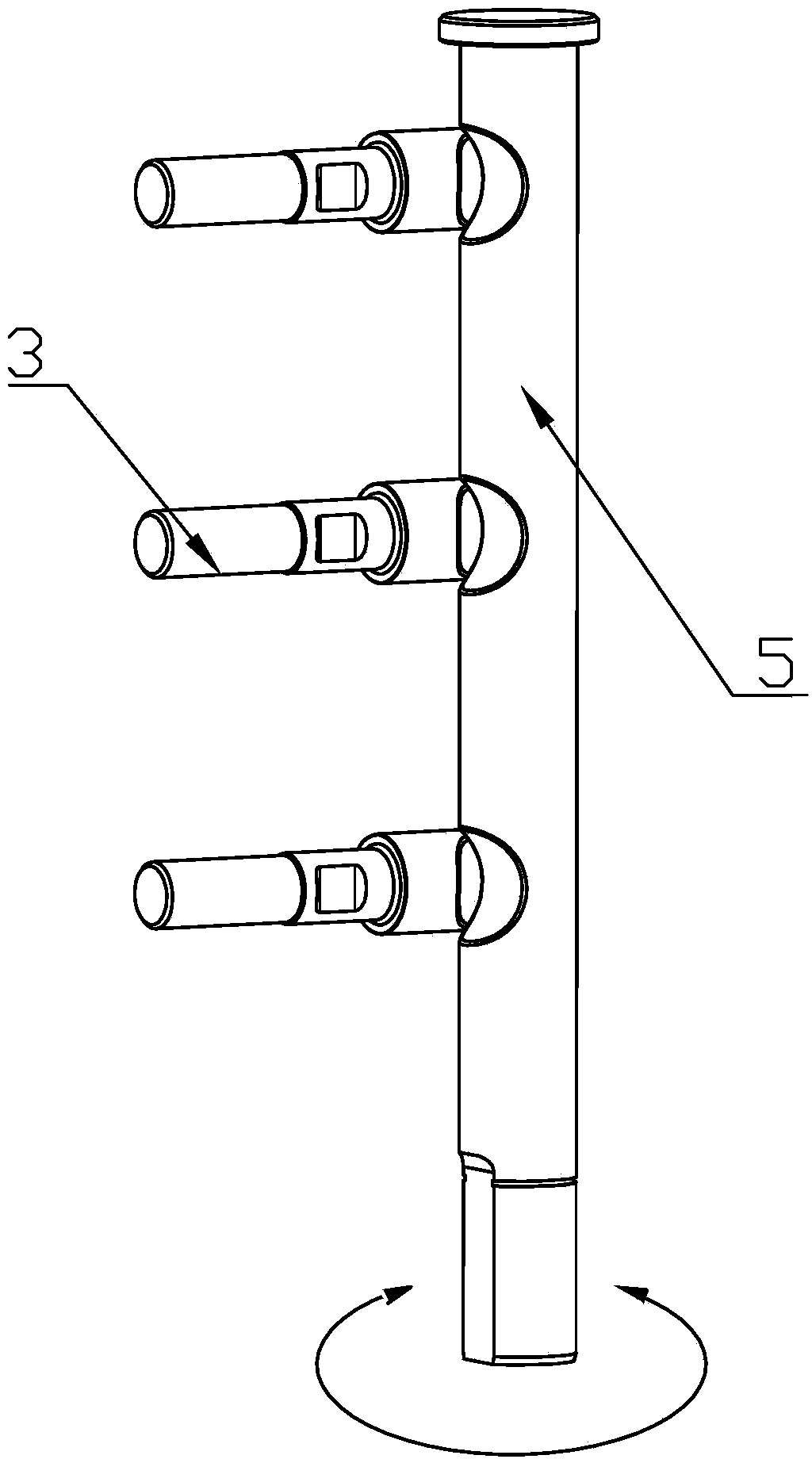
[0026] refer to Figure 1 to Figure 4 , a rotary mold clamping mechanism, which includes a fixed mold base 2 an...


PUM


Abstract

The invention discloses a rotation type mold locking mechanism. The rotation type mold locking mechanism comprises a fixed mold frame and a movable mold frame, wherein the movable mold frame is provided with a plurality of mold locking rods, the fixed mold frame is provided with a plurality of positioning holes, a locking device is arranged between the mold locking rods and the positioning holes, and the movable mold frame and the fixed mold frame are locked or unlocked due to the cooperation of the mold locking rods, the positioning holes and the locking devices so as to clamp or release blow bottles; the locking device comprises rod gaps or rod bulges in or on the mold locking rods and a rotating shaft, shaft gaps are formed in the parts, coinciding with the positioning holes, of the rotating shaft, and a rotating mechanism for driving the rotating shaft to rotate is arranged at the lower end of the rotating shaft. According to the rotation type mold locking mechanism, the unlocking and locking between the fixed mold frame and the movable mold frame are realized by controlling the rotation angle position of the rotating shaft and by virtue of the rotating shaft on the fixed mold frame and the mold locking rods on the movable mold frame; a mold is directly locked by virtue of the shaft gaps or shaft bulges in or on the rotating shaft as well as the rod gaps in the mold locking rods, so that the transition power transfer is reduced, linear motion is replaced by rotary motion, and the rotation type mold locking mechanism can stably and reliably work.

Description

technical field [0001] The invention relates to a rotary mold locking mechanism, in particular to a rotary mold locking mechanism of a bottle blowing machine. Background technique [0002] With the rapid development of rotary blow molding machine technology in the world, the speed and stability of the machine continue to increase. As the core component of the machine, the mold base is the core component of the machine, and the rationality of its technical application has an important impact on the speed and stability of the machine. . [0003] As a mechanism for fixing and controlling the movement of the blowing mold of the rotary blow molding machine, the clamping rod was generally used to achieve the same function in the past. [0004] The mold locking method of the clamping rod type is to realize the unlocking and closing of the movable mold base through the control rod on the fixed mold base to drive the connecting rod and then drive the clamping pin to move up and down...

Claims


Application Information

Patent Timeline
Patent Type & Authority Applications(China)
IPC IPC(8): B29C49/56
Inventor 陈帮开
Owner 广州西力机械有限公司
Why Eureka
Try Eureka