Novel mechanical oil pump driven by main reduction gear

A mechanical oil pump and gear-driven technology, which is applied in the field of mechanical oil pumps, can solve problems such as difficult active lubrication work, complex installation structure of the connection structure, etc., and achieve the effect of simple and reasonable connection structure, simple structure and simple assembly

Active Publication Date: 2020-12-22
智新科技股份有限公司
View PDF15 Cites 0 Cited by
  • Summary
  • Abstract
  • Description
  • Claims
  • Application Information

AI Technical Summary

Problems solved by technology

The oil pump drives the inner rotor to rotate by driving the outer rotor, but it still needs an additional transmission mechanism to drive the outer rotor to rotate, and the con...

Method used


Image

  • Novel mechanical oil pump driven by main reduction gear
  • Novel mechanical oil pump driven by main reduction gear
  • Novel mechanical oil pump driven by main reduction gear

Examples


Embodiment 1

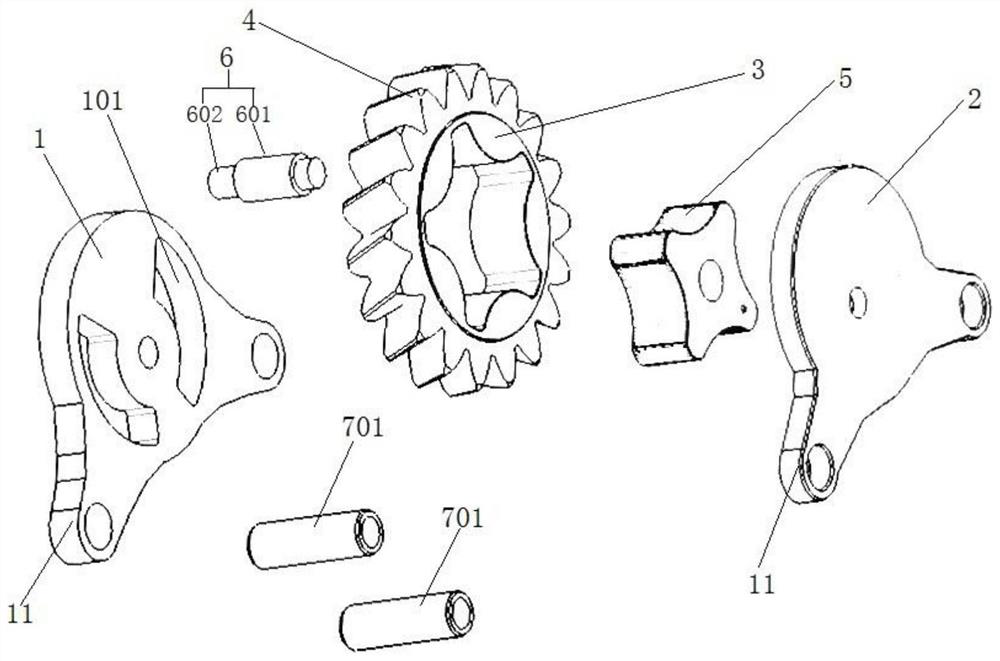
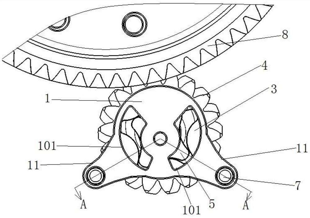
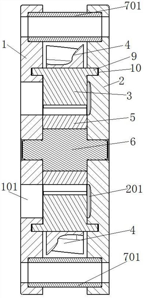
[0042] Such as Figure 1 to Figure 5 As shown, a new type of mechanical oil pump driven by the main reduction gear, the mechanical oil pump includes a first housing 1 and a second housing 2 that are mated and connected, and the first housing 1 and the second housing 2 is engaged with an outer rotor 3, the outer circumference of the outer rotor 3 is provided with an external tooth structure 4, and the outer diameter of the external tooth structure 4 is larger than that of the first housing 1 and the second housing 2, the outer tooth structure 4 is used to connect the main reduction gear 8; the inner circumference of the outer rotor 3 is equipped with an inner rotor 5, and the inner rotor 5 is connected to the The first housing 1 is connected to the second housing 2, the rotating pin 6 is coaxially arranged with the inner rotor 5, and the inner rotor 5 is eccentrically arranged with the outer rotor 6; the first The casing 1 and the second casing 2 are respectively provided with...

Embodiment 2

[0061] This embodiment provides the arrangement structure of the through holes on the first housing in the first embodiment.

[0062] Such as Figure 7 As shown, the through hole 101 and the counterbore 201 are two symmetrically arranged respectively, the through hole 101 and the counterbore 201 are fan-shaped holes, and a pair of adjacent radial sides of the fan-shaped holes The distance between them is smaller than the distance between the other adjacent radial sides, that is to say, the two fan-shaped holes are in a downwardly offset structure, which facilitates the pumping of the oil below.

[0063] Further, the arc radius of the short-side arc 14 of the fan-shaped hole is equal to the radius of the inner concave part of the inner rotor 5, that is, the radius at the minimum outer diameter 15 of the inner rotor; the long-side arc of the fan-shaped hole The arc diameter of 12 is equivalent to the radius of the concave part of the inner circumference of the outer rotor 3 , a...

Embodiment 3

[0065] The difference between this embodiment and the first embodiment lies in providing another structure of the first casing and the second casing.

[0066] Such as Figure 8 As shown, both the first housing 1 and the second housing 2 have three connecting lugs 11, the three connecting lugs 11 are arranged at intervals of 90 degrees, and the arrangement of the three connecting lugs 11 The stability of the connection and installation of the mechanical oil pump can be further improved.


PUM


Abstract

The invention discloses a novel mechanical oil pump driven by a main reduction gear. The novel mechanical oil pump comprises a first shell and a second shell which are connected in a matched mode; anouter rotor is clamped between the first shell and the second shell; an outer gear structure is arranged on the outer circumference of the outer rotor; the outer diameter of the outer gear structure is larger than the radial size of the first shell and the radial size of the second shell, and the outer gear structure is used for being connected with the main reduction gear; an inner rotor is installed on the inner circumference of the outer rotor and connected with the first shell and the second shell on the two sides in the axial direction through rotating pins; a plurality of corresponding connecting lugs are arranged in the circumferential direction of the first shell and the circumferential direction of the second shell respectively and connected through positioning pin assemblies; andthe positioning pin assemblies are further used for fixedly installing the mechanical oil pump. The mechanical oil pump of the invention is simple in structure, convenient to install, few in parts and low in cost; and the mechanical oil pump can be directly meshed with the main reduction gear, has a very good radial stress condition, and can have a very good NVH performance.

Description

technical field [0001] The invention relates to the technical field of mechanical oil pumps, in particular to a novel mechanical oil pump driven by a main reduction gear. Background technique [0002] The oil pump used for active lubrication inside the gearbox is generally composed of an inner rotor, an outer rotor, and upper and lower housings. Generally, the inner rotor is driven by the motor to change the meshing state of the inner and outer rotors, thereby changing the volume of the oil suction chamber and the oil pressure chamber, and then plays the role of pumping oil. The oil pump used in the existing DCT products of DGT is usually driven by the inner rotor driven by the motor. [0003] In addition, the current mechanical oil pump needs to design a pair of gears on the input shaft or output shaft separately and the transmission mechanism is long, because there is a difference in distance between the meshing part of the gears and the inner and outer rotors of the oil ...

Claims


Application Information

Patent Timeline
IPC IPC(8): F16H57/04F16N13/20F04C2/10F04C15/00
CPCF16H57/0436F16H57/0441F16N13/20F04C2/102F04C15/0061F16N2210/12
Inventor 俞彬斌徐汉明
Owner 智新科技股份有限公司
Why Eureka
Try Eureka