
Bridge expansion joint structure

A technology of expansion joints and bridges, applied in bridges, bridge parts, bridge construction, etc., can solve the problems of easy fracture of section steel, large amount of expansion, and low rigidity, so as to improve driving comfort, reduce impact, and buffer impact load Effect

Inactive Publication Date: 2014-07-30
HEFEI UNIV OF TECH
View PDF3 Cites 8 Cited by
  • Summary
  • Abstract
  • Description
  • Claims
  • Application Information

AI Technical Summary

Problems solved by technology

Among them, the plate rubber expansion joint has simple structure, convenient installation and strong versatility, but its rigidity is small and easy to deform, the rubber parts are easily damaged, the anchor is easily damaged, and it is easy to cause the expansion device to sink; the TST expansion joint effectively avoids or slows down the bridge head jump. Vehicle problems, but the filler is easy to bulge and sag under the long-term impact load of the vehicle, resulting in greater driving impact, aging and falling off after long-term use, cracking and water seepage, and erosion of the bridge span structure; Maurer expansion joints are currently the best. An expansion joint with a long service life, its swallow-shaped rubber belt is easy to replace, and can meet a series of requirements such as expansion and water stop
But its expansion and contraction is too large, the rubber strip is cracked or extruded, and its section steel is prone to breakage

Method used


Image

  • Bridge expansion joint structure
  • Bridge expansion joint structure
  • Bridge expansion joint structure

Examples


Embodiment Construction

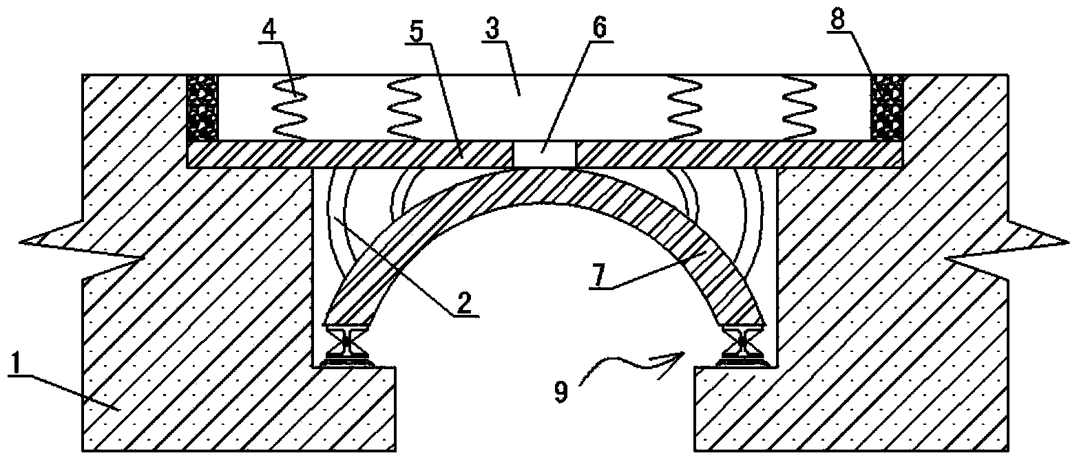
[0023] See figure 1 In this embodiment, the structural form of the bridge expansion joint is: for the expansion joint between the adjacent section beams 1, the top plane of the expansion plate 5 arranged in the expansion joint is lower than the height of the bridge deck to form a concave platform, A replaceable paving layer 3 is set on the concave platform, and the top surface of the paving layer 3 is level with the bridge deck. The reserved gap between the paving layer 3 and the bridge deck is filled with foam caulking material 8 , Foam joint filler 8 is light in weight, high in specific strength, can absorb impact load, has good heat insulation and sealing performance; a support structure is provided at the bottom of the expansion plate 5, and the support structure is to erect an arch between the beams 1 on both sides of the expansion joint The supporting body 7 is provided with supporting rods 2 on the arched supporting body 7. The telescopic plate 5 is jointly supported by t...


PUM


Abstract

The invention discloses a bridge expansion joint structure. The structure is characterized in that for an expansion joint positioned between beam bodies in adjacent sections, the top plane of an expansion plate arranged in the expansion joint is lower than a bridge floor so as to form a concave platform; a replaceable pavement layer is arranged on the concave platform; the top surface of the pavement layer is enable to be leveled with the bridge floor; a supporting structure is arranged at the bottom of the expansion plate; the supporting structure adopts an arched supporting body erected between beam bodies on two sides of the expansion joint; all supporting rods are arranged on the arched supporting body; the expansion plate is supported by step surfaces, the supporting rods and the arched supporting body of the beam bodies on the two sides of the expansion joint; the arched supporting body and the supporting rods adopt steel structure pieces; the pavement layer adopts an elastic material layer. The structure can rapidly absorb kinetic energy after suffering impact load, effectively buffers the impact load, prolongs the service life, and improves the driving comfort.

Description

Technical field [0001] The invention relates to a bridge expansion joint structure and belongs to the technical field of bridge engineering. Background technique [0002] With the seasons and the temperature changes day and night, the middle beam structures of simply supported bridges and continuous bridges exhibit thermal expansion and contraction. For this reason, it is necessary to set expansion joints between adjacent bridge panels to meet the expansion and rotation deformation of the bridge superstructure caused by temperature changes, concrete creep, dry shrinkage, and loads. Bridge expansion joints should have the characteristics of durability, waterproofing and convenient construction, and it is required to ensure driving comfort. [0003] In the prior art, expansion joints widely used in bridge engineering include plate rubber expansion joints, TST expansion joints, and Maurer expansion joints. Among them, the plate rubber expansion joint has simple structure, convenient...

Claims


Application Information

Patent Timeline
Patent Type & Authority Applications(China)
IPC IPC(8): E01D19/06
Inventor 董满生李满储诚富李淑琴
Owner HEFEI UNIV OF TECH
Learn More