Spacing pressing mechanism

A technology of limit and limit column, which is applied in the direction of mechanical equipment, engine components, engine sealing, etc., and can solve problems such as single function and narrow use area

Inactive Publication Date: 2014-07-30
海门市飞鹭制冷设备有限公司
View PDF6 Cites 0 Cited by
  • Summary
  • Abstract
  • Description
  • Claims
  • Application Information

AI Technical Summary

Problems solved by technology

[0002] In the prior art, there are some pressure-applying mechanisms, which are often simple in structure and single in function
The existing pressure applying mechanism does not have the dual functions of surface pressure and point pressure, and the use surface is narrow

Method used


Image

  • Spacing pressing mechanism
  • Spacing pressing mechanism

Examples


Embodiment Construction

[0016] The preferred embodiments of the present invention will be described in detail below in conjunction with the accompanying drawings, so that the advantages and features of the present invention can be more easily understood by those skilled in the art, so as to define the protection scope of the present invention more clearly.

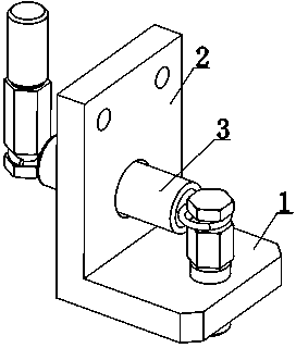
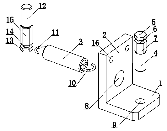
[0017] Such as Figure 1 to Figure 2 As shown, a position-limiting pressure applying mechanism includes a pressure block 1 and a support plate 2 connected to the pressure block 1. The pressure block 1 and the support plate 2 are arranged in an L-shape, and the pressure block 1 and the support plate 2 are integrated. , the briquetting block 1 is provided with a perforation 9, the perforation 9 is plugged with the first pressure column 4, the end of the first pressure column 4 is provided with a first buckle cap 5, and the connection position between the first buckle cap 5 and the first pressure column 4 The outer peripheral surface is provided wit...


PUM


Abstract

The invention discloses a spacing pressing mechanism which comprises a pressing block and a support plate connected with the pressing block, wherein the arrangement of the pressing block and the support plate takes an L shape; the pressing block and the support plate adopt an integral structure; a penetration hole is formed in the pressing block; a first compression leg is inserted in the penetration hole; a first buckle cap is arranged at the end part of the first compression leg; a first catching groove is formed in the outer peripheral surface in the joint of the first buckle cap and the first compression leg; an insertion hole is formed in the support plate; a force transmission shaft is inserted in the insertion hole; a first fastener is arranged at one end of the force transmission shaft; a second fastener is arranged at the other end of the force transmission shaft; the first fastener is bucked in the first catching groove; the other end of the force transmission shaft is connected with a second compression leg; a second buckle cap is arranged at the end part of the second compression leg; a second catching groove is formed in the outer peripheral surface in the joint of the second buckle cap and the second compression leg; the second fastener is bucked in the second catching groove. According to the spacing pressing mechanism, the pressing effect can be achieved, the plane can be pressed by the pressing block, the point can be pressed by the first compression leg, the water-proof rubber and the like can be flattened and the air tightness is better.

Description

technical field [0001] The invention relates to a pressure applying mechanism, in particular to a position-limiting pressure applying mechanism. Background technique [0002] In the prior art, there are some pressure exerting mechanisms, which are often simple in structure and single in function. The existing pressure applying mechanism does not have the dual functions of surface pressure application and point pressure application, and the use area is narrow. Contents of the invention [0003] The present invention mainly solves the technical problems existing in the prior art, so as to provide a pressure-applying function. The pressing block applies pressure to the plane, and the first pressure column applies pressure to points, so that the waterproof rubber can be flattened. Better airtight limit pressure mechanism. [0004] Above-mentioned technical problem of the present invention is mainly solved by following technical scheme: [0005] A position-limiting pressure...

Claims


Application Information

Patent Timeline
IPC IPC(8): F16B1/04F16J15/00
Inventor 谢娟
Owner 海门市飞鹭制冷设备有限公司
Why Eureka
Try Eureka