
Submarine high-pressure oil gun

A high-pressure machine, latent technology, applied in the direction of mechanical equipment, engine components, engine lubrication, etc., can solve the problems of incomplete oil use, poor airtightness, no oil pumping, etc., to achieve thorough oil use and flexible operation , the effect of convenient refueling

Inactive Publication Date: 2009-09-09
吴定华
View PDF0 Cites 0 Cited by
  • Summary
  • Abstract
  • Description
  • Claims
  • Application Information

AI Technical Summary

Problems solved by technology

[0003] But the machine oil gun of this structure at present, because its oil filling device all is positioned at the outside of oil storage device except suction pipe, is arranged on the top of oil tank, therefore there is the problem of tightness between three except gun body, connection cover and oil tank In addition, it is difficult to ensure the sealing between the spray rod and the gun body, the gun body piston cylinder and the piston, so the oil will leak from the gap during use.
In addition, due to the poor airtightness, the air will enter the oil tank through the gap, causing no oil to be pumped out, so that the oil gun cannot work
In addition, the oil filling device absorbs oil through the suction pipe in the oil tank, so it is difficult to suck the oil at the bottom, the oil is not used thoroughly, and there is waste

Method used


Image

  • Submarine high-pressure oil gun
  • Submarine high-pressure oil gun
  • Submarine high-pressure oil gun

Examples


Embodiment Construction

[0015] The present invention will be further described in detail below in conjunction with the accompanying drawings and embodiments.

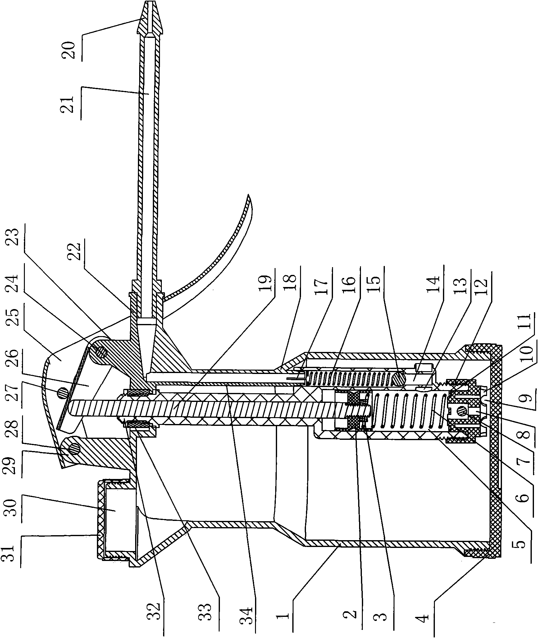
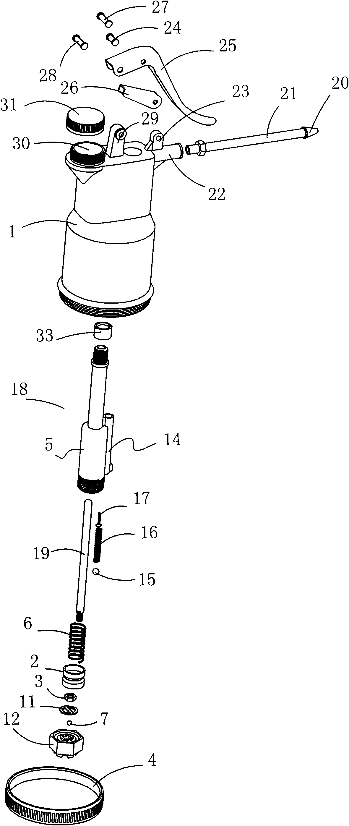
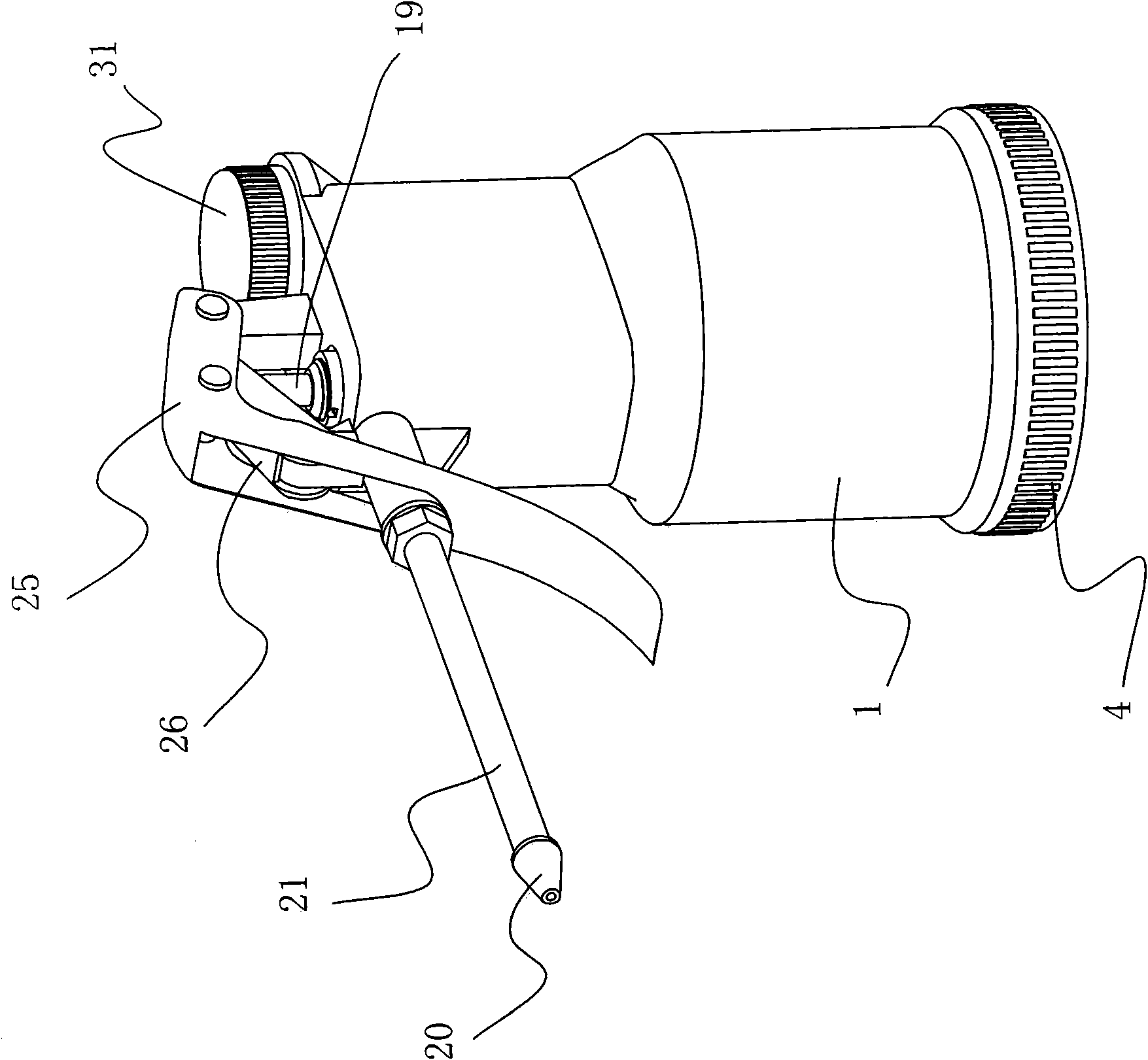
[0016] to combine Figure 1-Figure 3 As shown, the latent high-pressure oil gun of the present invention is composed of two parts, the oil storage device and the oil injection device, wherein:

[0017] Oil storage device is an oil tank 1, the bottom of oil tank is open, and a bottom cover 4 is installed, can adopt thread connection between bottom cover 4 and oil tank 1, and seal with sealing ring or sealant. The top of the oil tank 1 is formed with an opening for the piston rod 19 to pass, a gun barrel 22 (oil delivery pipe hole) connected with the spray bar, a filling hole 30 and two screws for pivoting the wrench 25 and the transmission member 26. Boss 29,23, two bosses 29,23 are all shaped on shaft holes. A sealing cover 31 is housed on the filling hole 30, and machine oil is added in the oil tank 1 from this hole. The inside of the oil ...


PUM


Abstract

A submarine high-pressure oil gun comprises an oil storage unit and an oiling device; wherein, the oiling device comprises an oil pump assembly arranged in an oil tank; the pump body of the oil pump assembly is provided with two longitudinally arranged oil chambers which are communicated with each other via an opening on the side; one of the two oil chambers is an oil inlet chamber; a piston is arranged in the oil inlet chamber; the bottom of the piston is provided with a return spring; a piston rod connected with the piston is connected with a wrench on the oil tank by transmission after passing through the opening of the oil tank; a sealing element is arranged between the piston rod and the opening of the oil tank; the opening on the bottom of the oil inlet chamber is connected with a screw cap which is provided with oil-absorption holes; a check valve is installed in the oil-absorption hole; the other one of the two oil chambers is an oil outlet chamber which is internally provided with the check valve composed of a steel ball and a spring; an oil outlet channel communicated with a spray rod and the oil outlet chamber is arranged in the oil tank; the spray rod is hermetically connected with the opening of the oil outlet channel. The oiling device is built-in, thus eliminating leakage of rain and no oil produced due to poor leak tightness; in addition, the oil is ensured to be used thoroughly.

Description

technical field [0001] The invention relates to an oil gun, which is used for lubricating and oiling machine equipment. Background technique [0002] The oil gun is a commonly used oiling tool, which is usually composed of an oiling device and an oil storage device. The oiling device often includes a gun body, a spray rod, a nozzle, a piston, a piston rod, a suction pipe and a wrench, etc. Among them, the gun body An oil-filled piston cylinder is made in the middle, and a piston and a return spring are installed in the piston cylinder, and the piston rod connected to the piston is matched with a wrench. The oil storage device is an oil tank, and a suction pipe is installed in the oil tank, and it links to each other with the gun body through a connecting cover. Pull the wrench by hand to compress the piston rod and piston, and the cylinder cavity of the oil injection piston becomes negative pressure, sucks oil from the oil tank through the suction pipe, then injects the oil...

Claims


Application Information

Patent Timeline
IPC IPC(8): F16N3/08
Inventor 吴定华
Owner 吴定华
Learn More