
Disc brake for bicycle
A disc brake and bicycle technology, applied in the field of bicycle brakes, can solve the problems of complex installation, poor stability and poor heat dissipation, and achieve the effects of stable overall structure, excellent structure and performance, and good heat dissipation.
- Summary
- Abstract
- Description
- Claims
- Application Information
AI Technical Summary
Problems solved by technology
Method used
Image

Examples
Embodiment Construction
[0041] The present invention will be further described in detail below in conjunction with the accompanying drawings, so that those skilled in the art can better understand the present invention, so as to make a more clear and definite definition of the protection scope of the present invention.
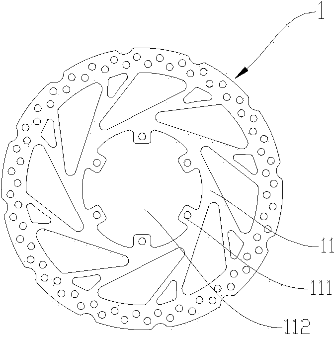
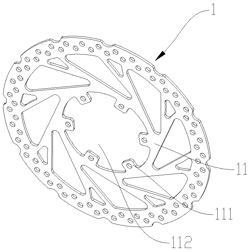
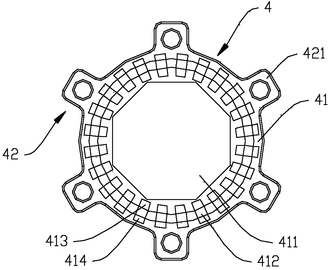
[0042] Referring to the accompanying drawings, the disc brake according to the present invention includes: a brake disc 1; a hub shaft, which has opposite first and second shaft ends, and the axis of the hub shaft is between the first shaft end and the second shaft end. The hub shell 2 includes opposite first hub shell ends 21 and second hub shell ends 22, the hub shell 2 is rotatably connected to the hub shaft; the brake disc connector 3 is arranged at the second On one hub shell end 21, the brake disc connector 3 has a tubular body 31 and an annular boss 32 formed by extending radially outward from the bottom periphery of the tubular body 31. The tubular body 31 has a space away...
PUM
 Abstract
Description
Claims
Application Information