
Low-ignition-voltage and high-power-output miniature detonator

A low-ignition, miniature technology, applied in weapon accessories, fuzes, offensive equipment, etc., can solve the problems of electric detonator safety current reduction, small size, high output power, etc., and achieve the effect of comprehensive performance improvement

Inactive Publication Date: 2014-01-08
BEIJING INSTITUTE OF TECHNOLOGYGY
View PDF3 Cites 0 Cited by
  • Summary
  • Abstract
  • Description
  • Claims
  • Application Information

AI Technical Summary

Problems solved by technology

There are obvious deficiencies in the design and use of existing bridge wire electric detonators: first, when a higher safety current (such as ≥100mA) is required, a higher firing voltage (such as ≥28V) and a higher The ignition energy (eg ≥ 10mJ)
However, with the reduction of ignition energy and the increase of ignition sensitivity, the safety current of the electric detonator is also reduced, which reduces the anti-static and anti-electromagnetic interference capabilities of the electric detonator, that is, improves the reliability of ignition at the expense of safety.
The design requirements of the two are a pair of opposite contradictions. It is difficult to better meet the development needs of micro-electromechanical systems and engineering blasting by using bridge wire electric detonators.
[0004] It can be said that although the existing traditional bridge wire detonator can easily meet the requirements of low ignition power, it is difficult to meet the comprehensive requirements of good electromagnetic safety, short ignition time, small size, firm structure, and high output power.
If semiconductor bridge components, tube shells, and energetic materials are used, parameters such as low ignition energy, short ignition time, and microstructure size are difficult to meet the technical requirements of the above MEMS

Method used


Image

  • Low-ignition-voltage and high-power-output miniature detonator
  • Low-ignition-voltage and high-power-output miniature detonator
  • Low-ignition-voltage and high-power-output miniature detonator

Examples


Embodiment Construction

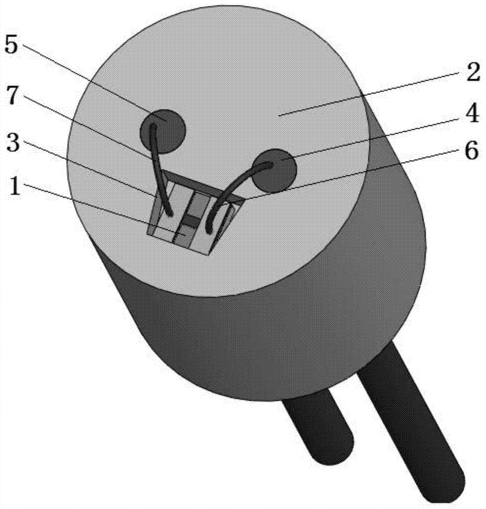
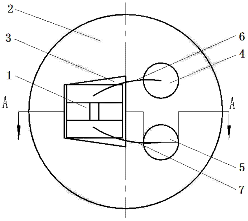
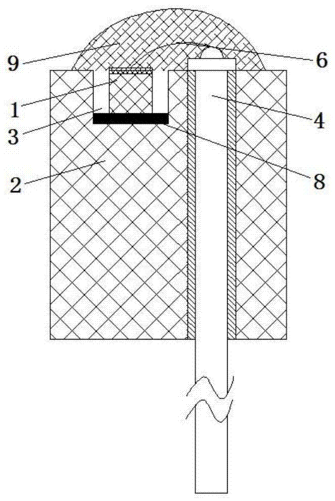
[0021] combine Figure 1-3 The low ignition voltage semiconductor bridge miniature ignition assembly includes three parts: semiconductor bridge transducer chip (1), asymmetric miniature ceramic electrode plug (2) and electrothermal sensitive ignition powder (9). Fix the rectangular semiconductor bridge transducer chip (1) in the trapezoidal groove (3) of the asymmetrical ceramic electrode plug (2) with an adhesive (8), adopt ultrasonic welding, and use bonding wires (6, 7) Connect the two metal pads on the semiconductor bridge transducer chip (1) to the two-leg electrodes (4, 5) of the ceramic electrode plug (2) respectively, so that the two leg electrodes of the electrode plug ( 4, 5) and the two metal pads of the semiconductor bridge transducer element to form a circuit path, and the semiconductor bridge transducer element is filled with electrothermal sensitive pyrotechnic powder (9) refine the neutral trinitroresorcinol lead to form an ignition component .

[0022] Fig...


PUM

PropertyMeasurementUnit
Diameteraaaaaaaaaa
Heightaaaaaaaaaa
Thicknessaaaaaaaaaa

Abstract

The invention discloses a low-ignition-voltage and high-power-output miniature detonator. The low-ignition-voltage and high-power-output miniature detonator mainly comprises a foot line, a ceramic electrode plug, a detonator shell, a semiconductor bridge chip, an ignition explosive, a primary explosive and a high explosive. The Cl-20 high explosive and the carboxymethyl cellulose lead azide primary explosive are sequentially pressed into the detonator shell to increase the axial output power of the miniature detonator, and a semiconductor bridge ignition component is fixed at a mouth part of the detonator shell by performing a detonator shell necking-in process and coating a sealant at the mouth part. The technical indicators of the miniature detonator disclosed by the invention are characterized in that the minimum full-ignition voltage is as low as 3.83V (10 micro F), the minimum full-ignition energy is 0.074mJ, the safe current is not less than 200mA, the size of the detonator is not more than phi 2.5*4 mm, and when the output detonation pressure of the detonator is tested by a manganin pressure gauge, the maximum output power of the miniature detonator achieves 13-15 GPa. Compared with the technical indicators of an existing bridge wire type electric detonator, the comprehensive performance of the detonator is greatly improved. The low-ignition-voltage and high-power-output miniature detonator disclosed by the invention is suitable for design of explosive trains of micro-electromechanical systems requiring low ignition voltage and high power output.

Description

Technical field [0001] The patent of the present invention relates to a miniature detonator, especially a semiconductor bridge microdetonator capable of reliable ignition under low ignition voltage input conditions and miniaturized volume. Background technique [0002] The detonator is an important part of the ammunition explosion sequence and engineering blasting explosion sequence, generally including ignition components, priming charges, sub-explosives and shells. The ignition components of traditional detonators generally use the bridge wire as the energy-transforming element. The bridge wire is welded between two metal legs. The detonator is ignited, and the detonator will detonate the strong explosive after realizing rapid combustion to detonation, output detonation and then complete the detonator function. There are obvious deficiencies in the design and use of existing bridge wire electric detonators: first, when a higher safety current (such as ≥100mA) is required,...

Claims


Application Information

Patent Timeline
IPC IPC(8): F42C19/12
Inventor 严楠鲍丙亮何爱军曾雅琴娄文忠焦清介温玉全任慧
Owner BEIJING INSTITUTE OF TECHNOLOGYGY
Learn More