
Contactless smart card swing test method and device

A non-contact, testing device technology, applied in the field of mobile communication, can solve the problems of affecting the test effect, difficult to locate time and location, and difficult to locate, so as to save human resource costs, improve test efficiency, and facilitate daily operation.

Inactive Publication Date: 2014-07-30
EASTCOMPEACE TECH
View PDF11 Cites 8 Cited by
  • Summary
  • Abstract
  • Description
  • Claims
  • Application Information

AI Technical Summary

Problems solved by technology

[0004] 1. The communication speed between the contactless card and the card reader is very fast, and the speed of hand movement is too slow, which will affect the test results, and the test results have no reference value;
[0005] 2. And if the card is damaged, it is difficult to locate the specific time and location of the damage, so it is difficult to find the cause of the card damage (the problem is more difficult to locate);
[0006] 3. During the testing process, the intensity and speed of swiping cards by human hands are not the same, which also affects the test effect, making the test results not of reference value

Method used


Image

  • Contactless smart card swing test method and device
  • Contactless smart card swing test method and device
  • Contactless smart card swing test method and device

Examples


Embodiment 1

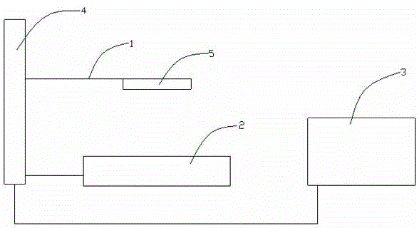
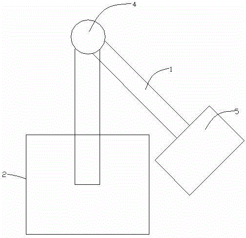
[0028] This embodiment provides a non-contact smart card swiping test device, such as figure 1 and figure 2 shown, which includes:

[0029] Manipulator 1, contactless card reader 2 and controller 3.

[0030] One end of the manipulator 1 is fixed on the upper end of a support column 4, the other end is used to fix the smart card 5 to be tested, and the other end can swing in the horizontal direction.

[0031] The non-contact card reader 2 is fixed below the manipulator 1, and the controller 3 is in signal communication or line communication with the non-contact card reader 2 for controlling the non-contact card reader 2. Send an instruction to the smart card 5 to be tested, and maintain the communication between the smart card 5 to be tested and the contactless card reader 2 .

[0032] The controller 3 communicates with the manipulator 1 in signal or line communication, and is used for controlling the swing of the manipulator 1 .

[0033] The manipulator 1 can drive the sm...

Embodiment 2

[0036] This embodiment provides a non-contact smart card swiping test device using the embodiment, which includes:

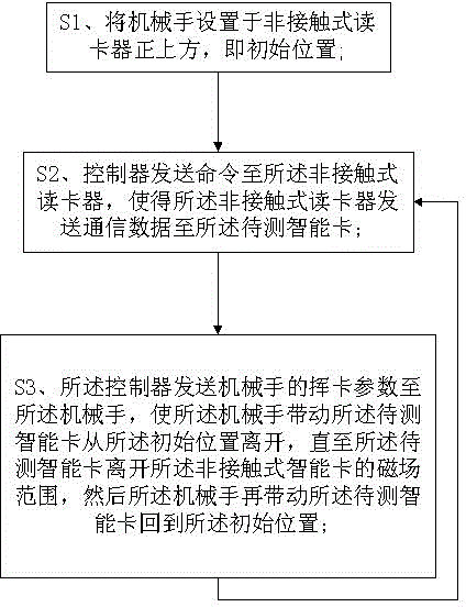
[0037] S1. Set the manipulator 1 directly above the contactless card reader 2, which is the initial position;

[0038] S2. The controller 3 sends a command to the contactless card reader 2, so that the contactless card reader 2 sends communication data to the smart card 5 to be tested;

[0039] S3. The controller 3 sends the card swiping parameters of the manipulator 1 to the manipulator 1, so that the manipulator 1 drives the smart card 5 to be tested to leave from the initial position until the smart card to be tested leaves the non-contact the magnetic field range of the type smart card 2, and then the manipulator 1 drives the smart card to be tested back to the initial position;

[0040] Go back to said S2, and so on.


PUM


Abstract

The invention provides a contactless smart card swing test method and device. The contactless smart card swing test device comprises a mechanical arm, a contactless card reader and a controller. One end of the mechanical arm is fixed, and the other end of the mechanical arm is used for fixing a smart card to be tested and can rotate in the horizontal direction. The contactless card reader is fixed under the mechanical arm, the controller is in signal or line connection with the contactless card reader and used for controlling that the contactless card reader sends an instruction to the smart card and keeping communication of the smart card and the card reader. The controller is in signal or line connection with the mechanical arm and used for controlling swing of the mechanical arm. The contactless smart card swing test method and device facilitates daily operation, can quickly find out problems and faults and improve the testing efficiency, accordingly saves the human resource cost and improves the product development efficiency.

Description

technical field [0001] The invention relates to the field of mobile communication, in particular to a non-contact smart card swiping test method and device for smart card detection. Background technique [0002] For companies engaged in contactless smart cards (such as bus cards, cards swiped in canteens), daily testing includes testing the performance of smart cards under abnormal operating conditions and damage by damage. Among them, one abnormal operation detection method is to remove the card suddenly during the communication process between the non-contact smart card (PICC) and the card reader (PCD), and check whether the card is damaged after repeated times. [0003] The commonly used method now is the manual test method of suddenly taking the card away when swiping the card. This method has too many defects: [0004] 1. The communication speed between the contactless card and the card reader is very fast, and the speed of hand movement is too slow, which will affect ...

Claims


Application Information

Patent Timeline
IPC IPC(8): G01R31/00
Inventor 宋魏杰施伟周张汉就
Owner EASTCOMPEACE TECH
Learn More