Method for measuring steady-state thermal resistance value of IGBT

A thermal resistance and steady-state technology, applied in the IGBT field, can solve problems such as uneven junction temperature distribution, and achieve the effect of saving test time and uniform chip temperature distribution

Inactive Publication Date: 2014-07-30
INST OF MICROELECTRONICS CHINESE ACAD OF SCI +1
View PDF2 Cites 14 Cited by
  • Summary
  • Abstract
  • Description
  • Claims
  • Application Information

AI Technical Summary

Problems solved by technology

[0005] The technical problem to be solved by the present invention is to provide a method for measuring the steady-state thermal resistance of the IGBT, which solves the technical problem in the prior art that the junction temperature is measured according to the IGBT through an electrical method, resulting in uneven distribution of the junction temperature

Method used


Image

  • Method for measuring steady-state thermal resistance value of IGBT
  • Method for measuring steady-state thermal resistance value of IGBT
  • Method for measuring steady-state thermal resistance value of IGBT

Examples


Embodiment Construction

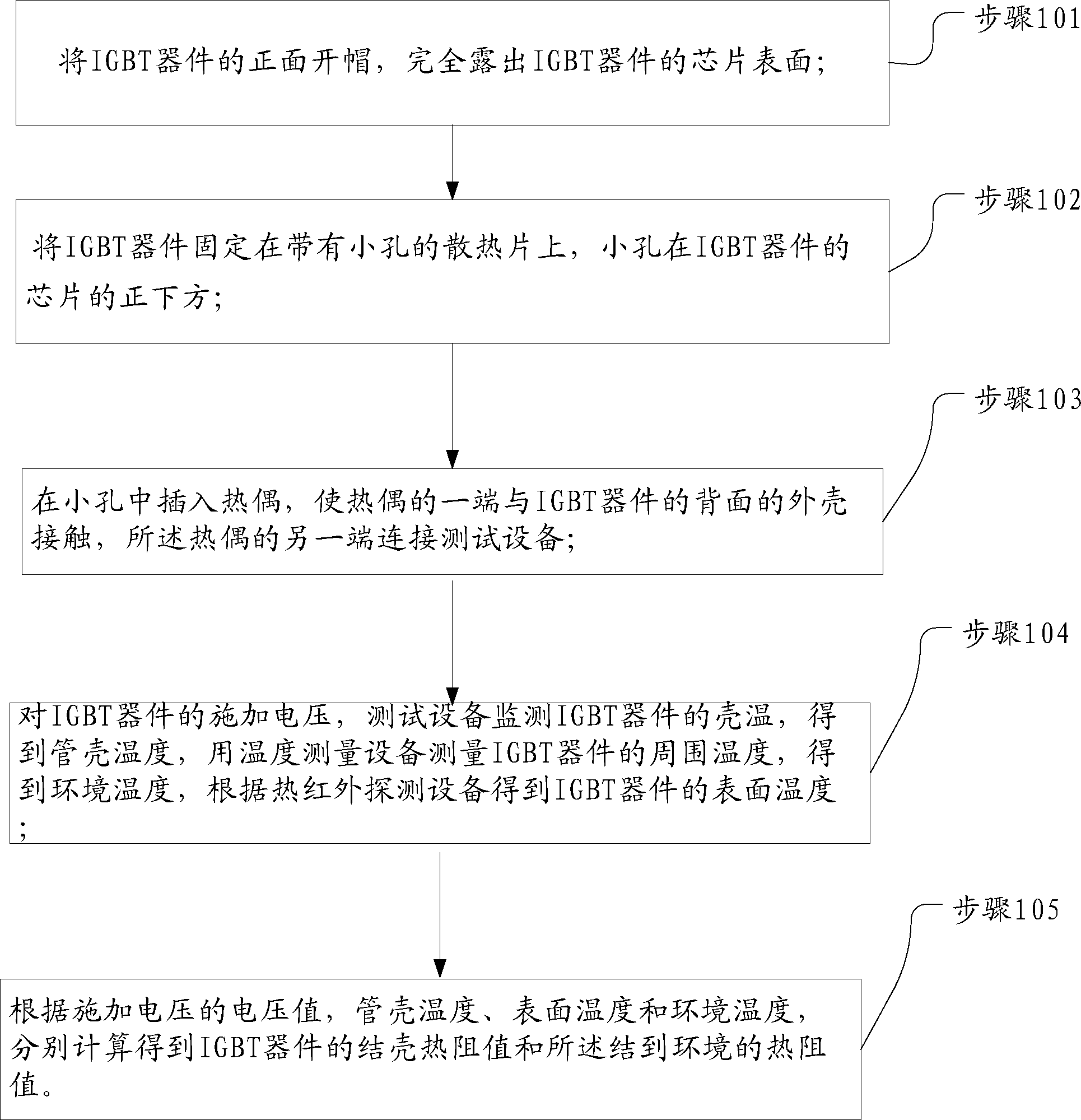
[0023] see figure 1 , a method for measuring the steady-state thermal resistance of an IGBT provided by an embodiment of the present invention includes the following steps:

[0024] Step 101: Uncap the front side of the IGBT device to completely expose the chip surface of the IGBT device;

[0025] Step 102: Fix the IGBT device on a heat sink with a small hole directly below the chip of the IGBT device;

[0026] Step 103: inserting a thermocouple into the small hole, making one end of the thermocouple contact the shell on the back of the IGBT device, and the other end of the thermocouple is connected to the test equipment;

[0027] Step 104: Applying voltage to the IGBT device, the test equipment monitors the case temperature of the IGBT device to obtain the case temperature, measures the ambient temperature of the IGBT device with a temperature measuring device, obtains the ambient temperature, and obtains the surface temperature of the IGBT device according to the thermal in...


PUM


Abstract

The invention relates to a method for measuring the steady-state thermal resistance value of an IGBT and belongs to the technical field of IGBTs. The method includes the first step of decapsulating the obverse side of the IGBT to enable the chip surface of the IGBT to be exposed completely, the second step of fixing the IGBT to a cooling fin with a small hole, the third step of inserting a thermocouple into the small hole, enabling one end of the thermocouple to make contact with a shell of the reverse side of the IGBT and enabling the other end of the thermocouple to be connected with a testing device, and the fourth step of calculating the junction-to-case thermal resistance value and the junction-to-ambient thermal resistance value of the IGBT respectively according to the voltage value of applied voltage, the case temperature, the surface temperature and the ambient temperature. A photoelectric sensor in a thermal infrared lens converts optical signals into electrical signals so as to monitor the surface temperature of a chip of a device to be measured, the chip can be improved according to distribution of temperatures on the surface of the chip after the chip is in a thermal equilibrium state, and the testing time can be shortened.

Description

technical field [0001] The invention belongs to the technical field of IGBTs, in particular to a method for measuring the steady-state thermal resistance of IGBTs. Background technique [0002] IGBTs are mainly used in the field of power electronics. When working at high power, a large amount of heat will be generated, which will directly affect the temperature rise and thermal stress of the device, resulting in shortened working life, and also affect the surrounding devices. Some surrounding equipment, components and components cannot work normally at higher temperatures. The temperature rise and thermal resistance of IGBT are one of the important parameters that affect its life and evaluate its reliability. [0003] The region between radio waves and visible light occurs. Among them, the part with a wavelength of 0.78-1.5 μm is called near-infrared, the part with a wavelength of 1.5-10 μm is called mid-infrared, and the part with a wavelength of 10-1000 μm is called far-...

Claims


Application Information

Patent Timeline
Patent Type & Authority Applications(China)
IPC IPC(8): G01R31/26
Inventor 佘超群胡爱斌成星高振鹏
Owner INST OF MICROELECTRONICS CHINESE ACAD OF SCI
Why Eureka
Try Eureka