Slot running device after cutting head of small bar and flying shear

A technology for cutting heads and bars, which is applied in the field of small-sized bar cutting and flying shears, and can solve problems such as no good solutions, and achieve the effects of simple structure, reliable collection, and extended service life

Inactive Publication Date: 2015-11-11
JIGANG GRP
View PDF9 Cites 0 Cited by
  • Summary
  • Abstract
  • Description
  • Claims
  • Application Information

AI Technical Summary

Problems solved by technology

[0003] Currently, there is no good solution

Method used


Image

  • Slot running device after cutting head of small bar and flying shear
  • Slot running device after cutting head of small bar and flying shear
  • Slot running device after cutting head of small bar and flying shear

Examples


Embodiment Construction

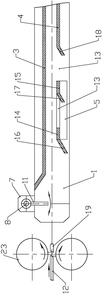
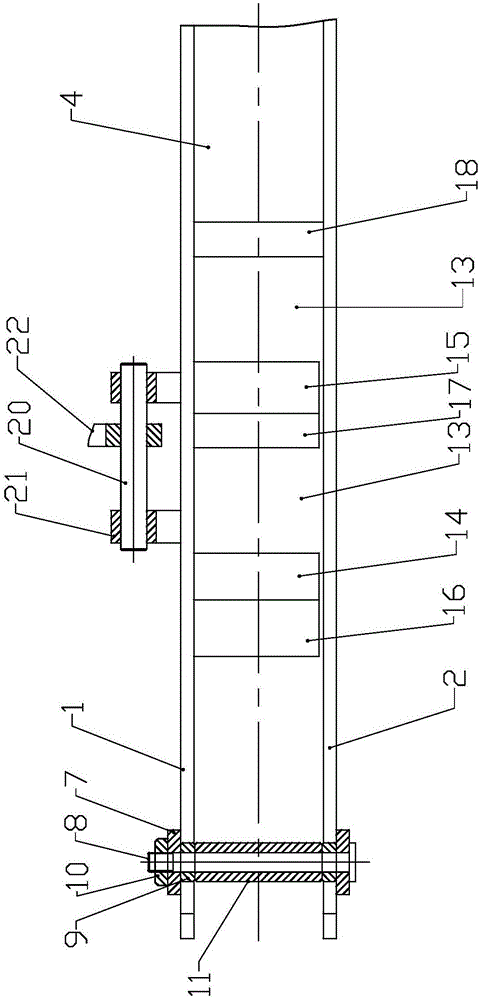
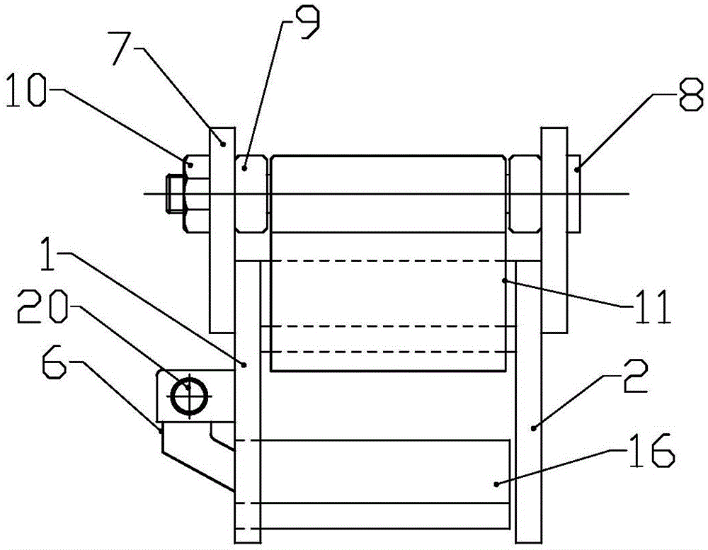
[0017] Refer to the attached figure 1 to attach image 3 The groove-running device after the small-sized bar cutting and flying shear of the present invention is described in detail below.

[0018] The rear trough running device of the small-sized bar cutting head flying shear of the present invention includes a rear trough running mechanism, and the rear trough running mechanism includes a left guard plate 1, a right guard plate 2, an upper guard plate 3, and a fixed bottom plate 4. The movable flap 5 and the movable flap turning drive mechanism 6, the upper guard 3 is arranged on the upper part between the left guard 1 and the right guard 2, the movable flap 5 and the fixed bottom plate 4 are respectively located at the lower part of the upper guard plate 3, the fixed bottom plate 4 is arranged on the rear side of the movable flap 5, and the left end of the movable flap 5 passes through the left guard plate 1 and the movable flap turning drive mechanism 6 Connected, the fr...


PUM


Abstract

The invention discloses a rear runner device of a flying crop shear for a small bar material and belongs to the production equipment of the small bar material. The rear runner device comprises a rear runner mechanism including a left-side protection plate, a right-side protection plate, an upper protection plate, a fixed base plate, a movable overturning plate and a movable overturning plate driving mechanism, wherein a blank head baffling device is arranged on the front side of the upper protection plate and comprises support plates, a shaft pin, a spacer bush, a locking unit and a baffle, and the baffle is arranged on the shaft pin; a leaking groove is formed in the middle of the movable overturning plate to divide the movable overturning plate into a front movable overturning plate and a rear movable overturning plate, and a front overturning plate baffle and a rear overturning plate baffle are respectively arranged on the front sides of the front movable overturning plate and the rear movable overturning plate; a leaking groove is further formed between the fixed base plate and the movable overturning plate, and a base plate guiding plate is arranged on the front side of the fixed base plate. The rear runner device has the characteristics that sheared blank heads can effectively fall into a blank head collection pit, the obstruction caused after the sheared blank heads of rolled blanks fly into a runner is avoided, and a 'steel accumulation accident' is further avoided.

Description

technical field [0001] The invention relates to the technical field of small-sized bar production equipment, in particular to a small-sized bar head-cutting flying shear and back-grooving device. Background technique [0002] In the prior art, a section of straight and closed running trough with a flap mechanism is arranged after the small-sized bar cutting head flying shear. After the cutting head flies to the shearing head, the billet cutting head falls into the billet head collecting tank at the lower space reserved by the shearing head and the running groove after cutting with the shearing inertia and self-weight. In actual work, due to the different specifications of rolling products and the shearing accuracy of the cutting head flying shear, the speed of the billet and the length of the sheared billet head are unstable. Therefore, the falling direction and falling distance of the billet head after shearing are also unstable, and sometimes the sheared billet head will ...

Claims


Application Information

Patent Timeline
Patent Type & Authority Patents(China)
IPC IPC(8): B21D43/20
Inventor 程涛王金华梁云彩邓扬玉秦栋王东夏永青李磊段旭飞王树马学者
Owner JIGANG GRP
Why Eureka
Try Eureka