Mechanical structure and movement mode of automatic assembly machine for long tail ticket holder

A technology of mechanical structure and long tail, applied in the field of mechanical structure and movement mode, can solve the problems of large machine volume and energy consumption, complex assembly mechanism, high labor intensity, etc. Effect

Active Publication Date: 2017-05-17
崔建忠
View PDF4 Cites 0 Cited by
  • Summary
  • Abstract
  • Description
  • Claims
  • Application Information

AI Technical Summary

Problems solved by technology

[0003] The purpose of the present invention is to address the above problems and provide a mechanical structure and movement mode of the long-tail ticket holder automatic assembly machine that simulates the movement of artificial fingers and wrists, so as to solve the problem of high labor intensity and low efficiency of long-tail ticket holder assembly at the present stage , while improving the complexity of the assembly mechanism, as well as the phenomenon of large machine volume and energy consumption

Method used


Image

  • Mechanical structure and movement mode of automatic assembly machine for long tail ticket holder
  • Mechanical structure and movement mode of automatic assembly machine for long tail ticket holder

Examples


Embodiment Construction

[0019] In order to make the above objects, features and advantages of the present invention more comprehensible, the present invention will be further described in detail below in conjunction with the accompanying drawings and specific embodiments.

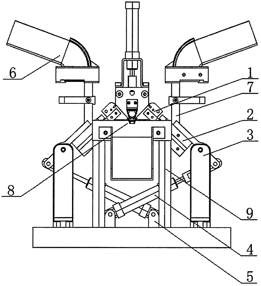
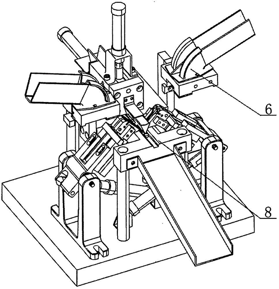
[0020] Please refer to figure 1 As shown in 2 to 2, in this embodiment, a mechanical structure and motion method for simulating the motion of artificial fingers and wrists, including left and right grippers 1, left and right finger cylinders 2, left and right finger cylinder seats 3, left and right rotating cylinders 4, left and right rotation Cylinder seat 5, left and right long tail ticket holder handle track 6, left and right long tail ticket holder handle track support 7, long tail ticket holder clip body track 8, long tail ticket holder clip body track support 9, described left and right grippers 1 are respectively connected with The left and right finger cylinders 2 are connected, and the left and right finger cylinders 2 c...


PUM


Abstract

The invention relates to a mechanical structure and a motion mode of an automatic binder clip assembly machine. The mechanical structure comprises left and right grippers, left and right finger air cylinders, left and right air cylinder seats, left and right rotating air cylinders, left and right rotating air cylinder seats, left and right binder clip handle rails, left and right binder clip handle rail supports, a binder clip body rail and a binder clip body rail support. During moving, the rotating air cylinders drive the finger air cylinders to rotate around the finger air cylinder seats and accordingly drive the grippers to turn an exit below the binder clip handle rail supported on the binder clip handle rail support and capture a binder clip handle. Meanwhile, the finger air cylinders move automatically to drive the grippers to capture and relieve by simulating human fingers, the binder clip handle is placed into the binder clip body on the binder clip body rail supported on the binder clip body rail support. The mechanical structure has the advantages that binder clip assembly efficiency can be remarkably improved, the structure of the automatic assembly machine is simplified, size is reduced and energy consumption is reduced.

Description

technical field [0001] The invention relates to a mechanical structure and a movement mode for simulating the movement of artificial fingers and wrists, which can realize automatic assembly of long tail bill holders. Background technique [0002] At present, most of the long-tail wallets are manually assembled, or non-pneumatic actuators such as motors are used for mechanical assembly of products. Manual assembly is adopted, which has high labor intensity and low production efficiency. Generally, the per capita assembly efficiency is 1000 pieces / hour. However, the mechanical assembly of products is carried out by using motors and other actuators. The mechanical structure is complex and the machine volume is large; the energy consumption is large, and it needs to consume 3000-17000W of electric energy; the efficiency is relatively low. Generally, the assembly of such an assembly machine Efficiency is less than 2400 / hour. Therefore, the assembly method of the long-tail walle...

Claims


Application Information

Patent Timeline
Patent Type & Authority Patents(China)
IPC IPC(8): B23P21/00
CPCB23P21/004
Inventor 崔建忠万金国
Owner 崔建忠
Why Eureka
Try Eureka