Detaching apparatus and detaching method

A peeling device, reference position technology, applied in chemical instruments and methods, lamination auxiliary operations, lamination, etc., can solve problems such as pattern damage, unstable boundary line shape, and peeling speed variation.

Active Publication Date: 2014-08-06
DAINIPPON SCREEN MTG CO LTD
View PDF6 Cites 16 Cited by
  • Summary
  • Abstract
  • Description
  • Claims
  • Application Information

AI Technical Summary

Problems solved by technology

When the moving speed of the boundary line, that is, the peeling speed changes, it is easy to damage the pattern due to stress concentration.
In particular, in the initial stage of the peeling process, since the shape of the boundary line is unstable, the peeling speed is likely to fluctuate due to the shape change of the boundary line
[0005] However, in the prior art described above, there is no structure capable of strictly controlling the peeling speed, and in particular, it is impossible to suppress fluctuations in the peeling speed due to local shape changes of the boundary line.
Therefore, from the aspect of preventing the damage of pattern etc., there is still room for improvement in the above-mentioned prior art.

Method used


Image

  • Detaching apparatus and detaching method
  • Detaching apparatus and detaching method
  • Detaching apparatus and detaching method

Examples


no. 1 approach

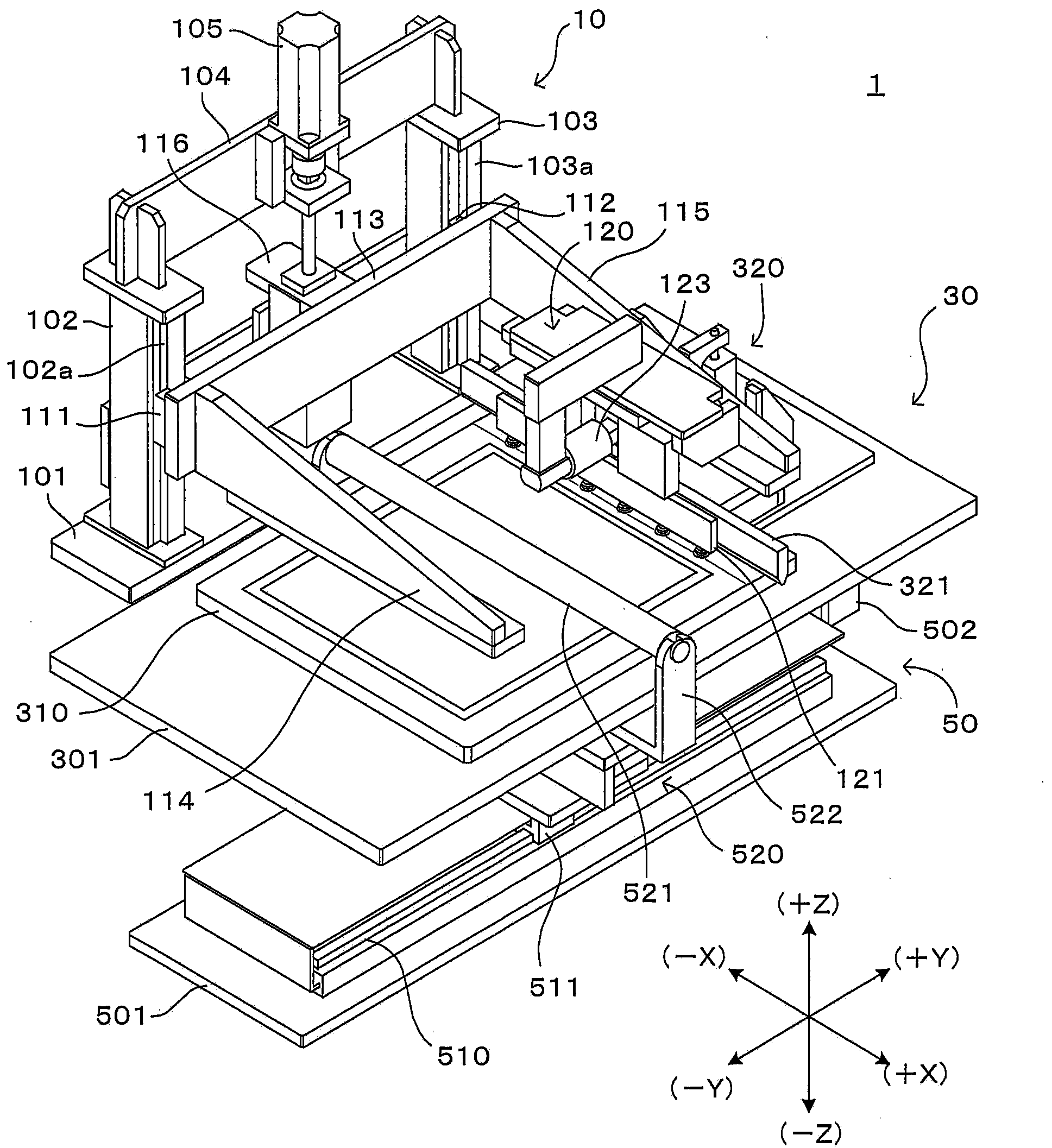
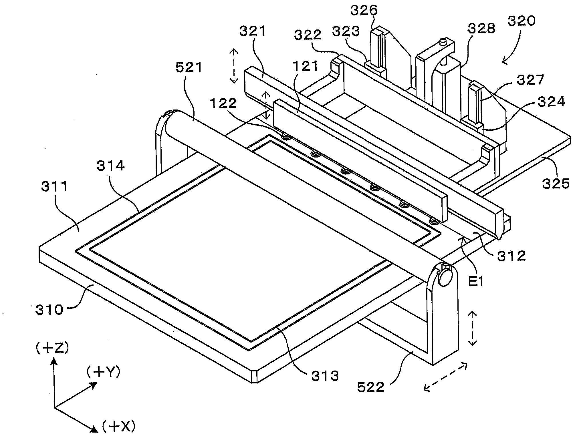
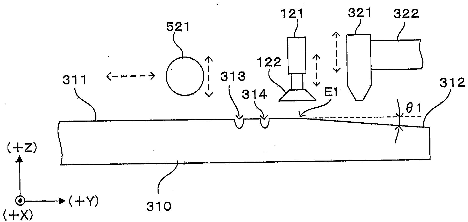
[0062] figure 1 It is a perspective view which shows 1st Embodiment of the peeling apparatus of this invention. In order to uniformly represent the directions in each figure, such as figure 1 Set the XYZ orthogonal coordinate axes as shown on the lower right. Here, the XY plane represents a horizontal plane, and the Z axis represents a vertical axis. More specifically, the +Z direction indicates a vertically upward direction. In addition, in each of the following figures, the size of each part may be appropriately enlarged or reduced to facilitate understanding of the invention. Therefore, in particular, the thicknesses of the substrates and blankets described later and the intervals between them may be shown larger than they actually are.

[0063] This peeling device 1 is a device for peeling two plate-shaped objects carried in with their main surfaces in close contact with each other. For example, it is used in a part of the pattern forming process of forming a predeter...

no. 2 approach

[0137] Figure 9 It is a perspective view which shows 2nd Embodiment of the peeling apparatus of this invention. In order to uniformly represent the directions in each figure, such as Figure 9 Set the XYZ orthogonal coordinate axes as shown on the lower right. Here, the XY plane represents a horizontal plane, and the Z axis represents a vertical axis. More specifically, the +Z direction indicates a vertically upward direction. In addition, in each of the following figures, the size of each part may be appropriately enlarged or reduced to facilitate understanding of the invention. Therefore, in particular, the thicknesses of the substrates and blankets described later and the intervals between them may be shown larger than they actually are.

[0138] With the stripping device 1 of the first embodiment ( figure 1 ) Similarly, this peeling device 2001 is a device for peeling two plate-shaped objects carried in with their main surfaces in close contact with each other. That...


PUM


Abstract

A detaching apparatus provided by the invention includes a first holder unit (310) that holds a first plate-like body (BL), a detachment starter unit (321) that bends one end part of the first plate-like body (BL) into a cylindrical or prismatic surface in a direction opposite to the second plate-like body (SB), thereby converting a part of an adhering region of the second plate-like body (SB) adhering to the first plate-like body (BL) into a detached region detached from the first plate-like body (BL) and forming a single and straight boundary line between the adhering region and the detached region, a second holder unit (122) that holds the second plate-like body (SB) formed with the detached region, and a separator unit that increases a distance between the first holder unit (310) and second holder unit (122) to separate the first plate-like body (BL) and second plate-like body (SB).

Description

technical field [0001] The present invention relates to a peeling device and a peeling method for peeling and separating two plate-shaped objects that are in close contact with each other. Background technique [0002] As a technique for forming a predetermined pattern or thin film on a plate-shaped object such as a glass substrate or a semiconductor substrate, a pattern or thin film (hereinafter referred to as "pattern, etc.") carried on another plate-shaped object is transferred to a substrate. In this technique, after transferring a pattern or the like from one to the other by bringing the two plate-shaped bodies into close contact, it is necessary to peel the two plate-shaped bodies without damaging the pattern or the like. [0003] For this purpose, for example, in the technology described in Japanese Patent Application Laid-Open No. 2008-287949, the two substrates bonded are kept in a horizontal posture, and the upper and lower plates are separated in a state of vacuum...

Claims


Application Information

Patent Timeline
Patent Type & Authority Applications(China)
IPC IPC(8): B32B38/10
CPCB32B43/006Y10T156/11Y10T156/1978
Inventor 川越理史正司和大芝藤弥生增市干雄上野博之上野美佳谷口和隆
Owner DAINIPPON SCREEN MTG CO LTD
Why Eureka
Try Eureka