Variable capacitive element, variable capacitive device, and method for driving the variable capacitive element

A variable capacitance and driving voltage technology, applied in variable capacitors, capacitors that change capacitance mechanically, capacitors that change the distance between electrodes, etc.

Inactive Publication Date: 2011-05-11
FUJITSU LTD
View PDF4 Cites 4 Cited by
  • Summary
  • Abstract
  • Description
  • Claims
  • Application Information

AI Technical Summary

Problems solved by technology

This limits the case of driving the vari...

Method used


Image

  • Variable capacitive element, variable capacitive device, and method for driving the variable capacitive element
  • Variable capacitive element, variable capacitive device, and method for driving the variable capacitive element
  • Variable capacitive element, variable capacitive device, and method for driving the variable capacitive element

Examples


no. 1 example

[0048] Figure 5 is a plan view showing an example of the structure of the variable capacitance device 1 according to the first embodiment; Figure 6-9 yes Figure 5 A cross-sectional view of the variable capacitance device 1 shown in . Figure 7 and 8 The same cross section is shown. Figure 7 shows a cross-section of the variable capacitive device 1 without moving the movable electrode 26, while Figure 8 A cross-section of the variable capacitance device 1 is shown with the movable electrode 26 moving.

[0049] refer to Figure 5 , the variable capacitance device 1 includes a variable capacitance element 2 , RF blocks 60 a - 60 c , a driving circuit 61 , and a driving circuit 62 . The variable capacitance element 2 includes a substrate 20 made of glass or silicon. On the substrate 20 are formed the first extraction electrode 21 , the second extraction electrode 22 , the first fixed electrodes 23 a - 23 c , the second fixed electrodes 24 a - 24 c , the movable electrode ...

no. 2 example

[0104] Figure 17 is a plan view showing the structure of the variable capacitance device 3 according to the second embodiment, Figure 18 is along Figure 17 The cross-sectional view of the variable capacitive device 3 taken by the line α1-α1.

[0105] The variable capacitive device 3 will be described below, focusing on the differences between the variable capacitive device 1 and the variable capacitive device 3 . Descriptions of the same parts as those in the variable capacitance device 1 are sometimes omitted.

[0106] refer to Figure 17 , the variable capacitance device 3 includes a variable capacitance element 4 , RF blocks 60 a - 60 c , a drive circuit 61 , and a drive circuit 62 . The variable capacitance element 4 includes a substrate 40 made of glass or silicon. On the substrate 40 are formed a fixed electrode 41 , a first extraction electrode 42 , a second extraction electrode 43 , a connection layer 44 , first movable electrodes 45 a and 45 b , second movable...


PUM


Abstract

A variable capacitive element includes a first fixed electrode and a second fixed electrode that are insulated from each other, a movable electrode arranged to face the first fixed electrode and the second fixed electrode, a dielectric layer provided between the movable electrode and the first fixed electrode as well as the second fixed electrode, a first wiring part for applying a first driving voltage to the first fixed electrode with reference to a potential of the movable electrode, and a second wiring part for applying a second driving voltage to the second fixed electrode with reference to the potential of the movable electrode, the second driving voltage having a polarity different from a polarity of the first driving voltage.

Description

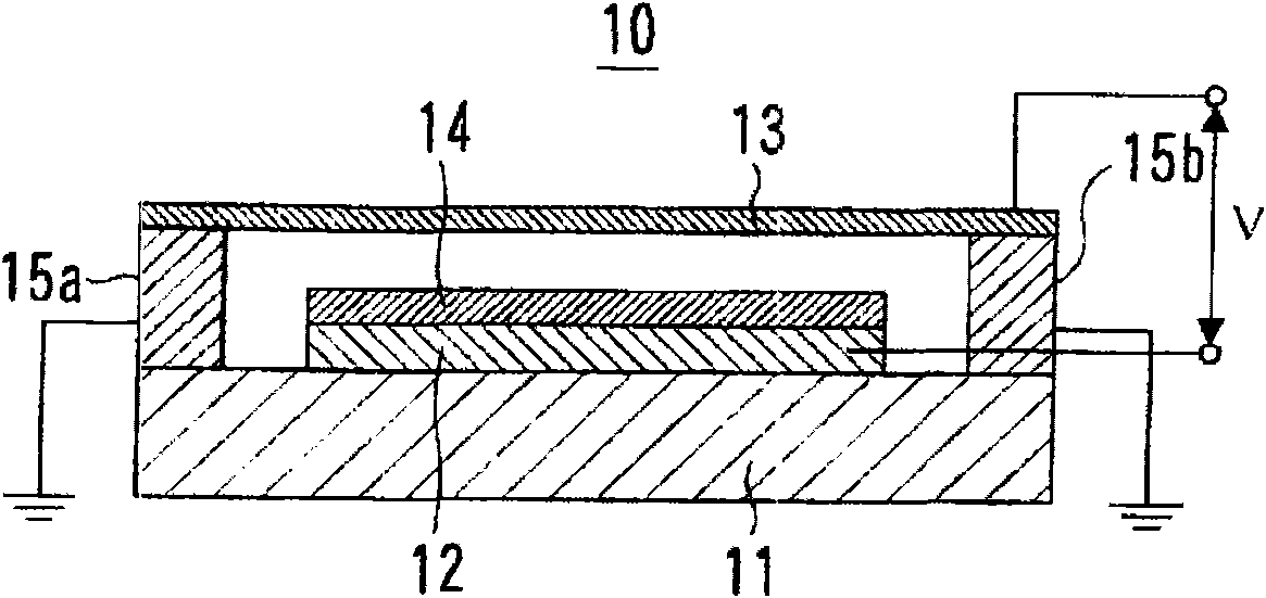
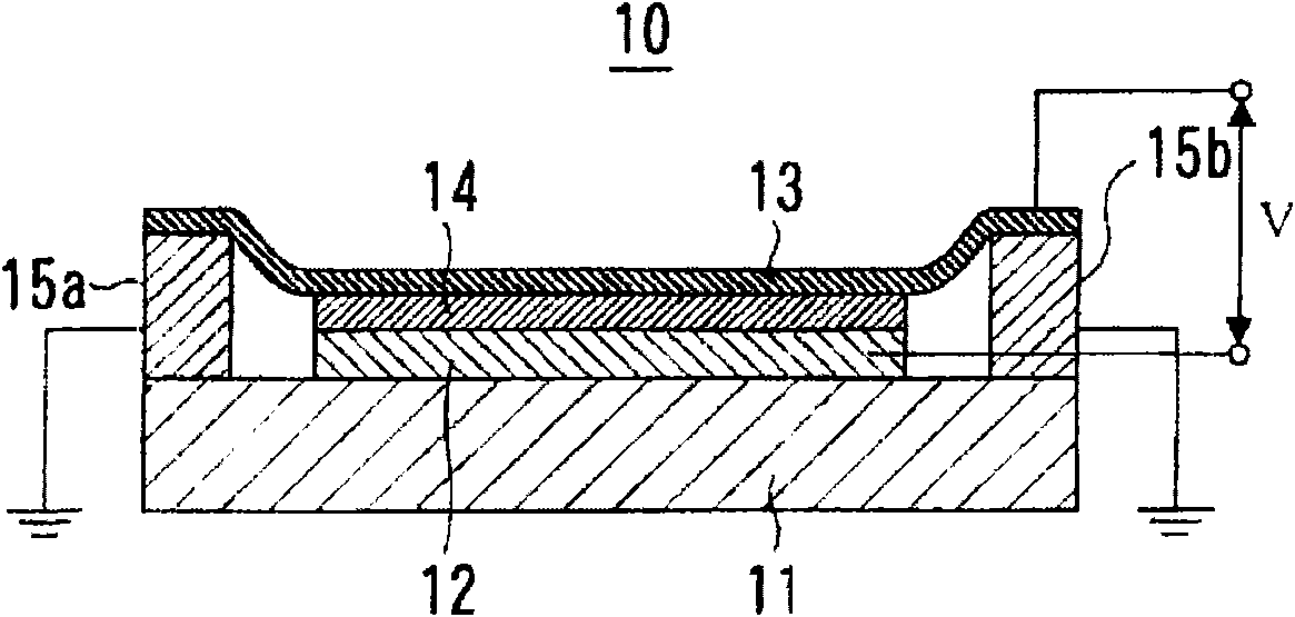
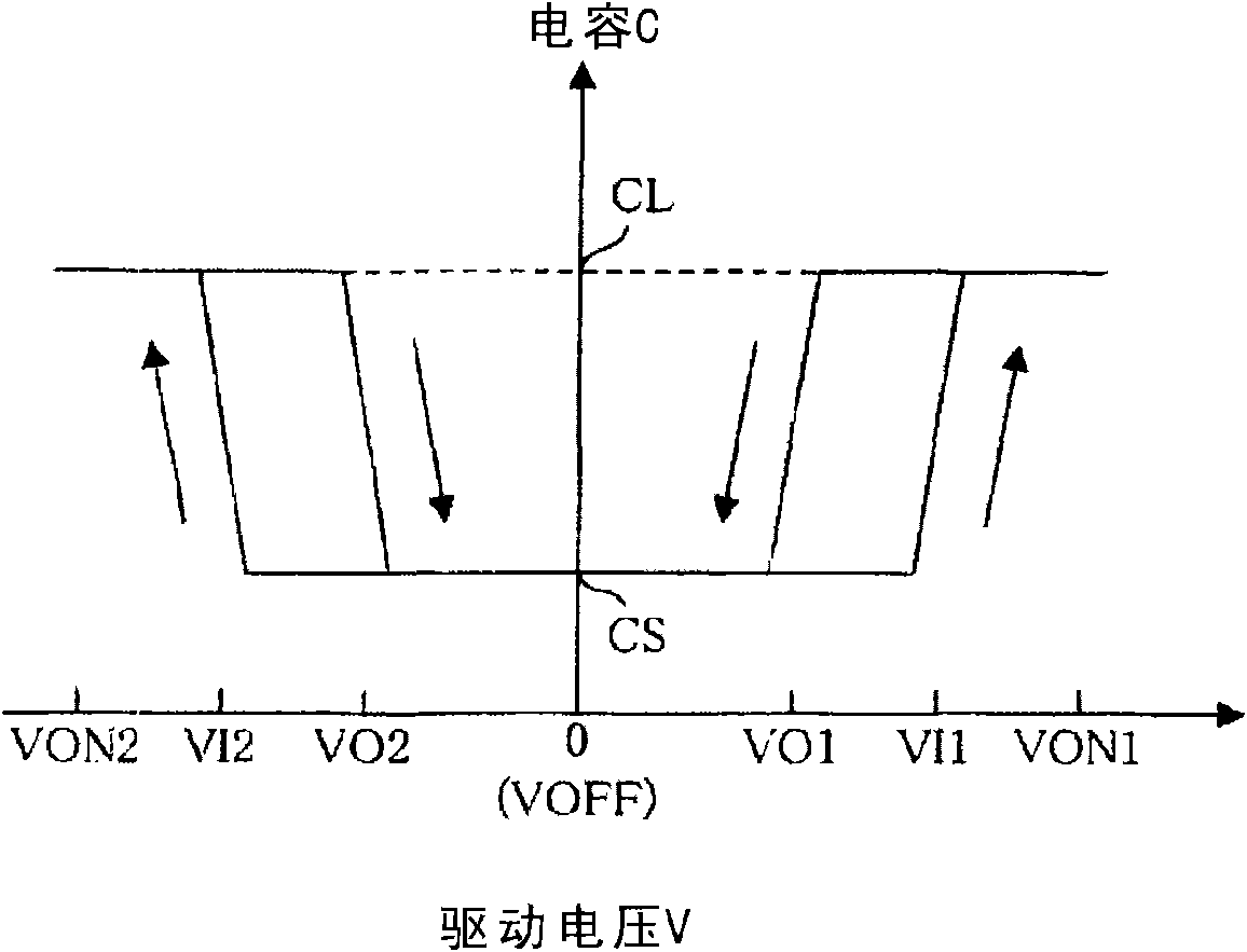
technical field [0001] Embodiments discussed herein relate to variable capacitance elements, and more particularly, to variable capacitance elements fabricated using microelectromechanical systems (MEMS) technology. Background technique [0002] Variable capacitance elements are components used in circuits such as variable frequency oscillators, tuned amplifiers, phase shifters, and impedance matching circuits. In recent years, more and more variable capacitance elements are installed in portable devices. [0003] Compared with varactor diodes, which are currently mainly used as variable capacitance elements, variable capacitance elements manufactured using MEMS technology can achieve high Q values ​​with low energy loss. Therefore, it is desired to develop variable capacitance elements manufactured using MEMS technology and put them into practical use. [0004] Hereinafter, a variable capacitance element manufactured using MEMS technology is simply referred to as a "varia...

Claims


Application Information

Patent Timeline
IPC IPC(8): H01G5/16
CPCH01G5/015H01G5/16
Inventor 岛内岳明今井雅彦胜木隆史上田知史
Owner FUJITSU LTD
Why Eureka
Try Eureka