pneumatic tire
A technology for pneumatic tires and tires, which is applied to the reinforcement layer of pneumatic tires, tire parts, tire tread/tread pattern, etc. The effect of shoulder defect wear
Active Publication Date: 2017-03-01
SUMITOMO RUBBER IND LTD
View PDF7 Cites 0 Cited by
- Summary
- Abstract
- Description
- Claims
- Application Information
AI Technical Summary
Problems solved by technology
However, even with such a pneumatic tire, there is room for further improvement in suppressing partial wear.
[0004] In addition, when the ground contact pressure of the shoulder land portion c is increased to suppress slipping with the road surface in order to suppress the wear of the shoulder defect, there is a possibility that slippage between the middle land portion f and the road surface is likely to occur, and the distance between the middle land portion f and the road surface may be reduced. The so-called track wear in which the outer end e produces guide rail-like partial wear
Method used
View moreImage
Smart ImageViewing Examples

Examples
Embodiment
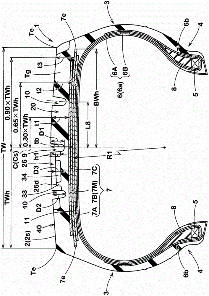
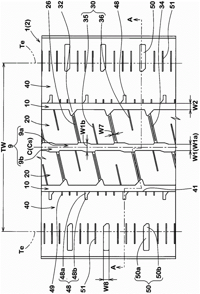
[0064] Based on the specifications in Table 1 a prototype was formed as figure 1 basic structure, and has figure 2 Pneumatic tires for light trucks with a tread pattern size of 185 / 65R15, and tested the partial wear of each test tire, the presence or absence of shoulder defect wear, the anti-slip performance and the heat dissipation of the shoulder land.
Login to View More PUM
 Abstract
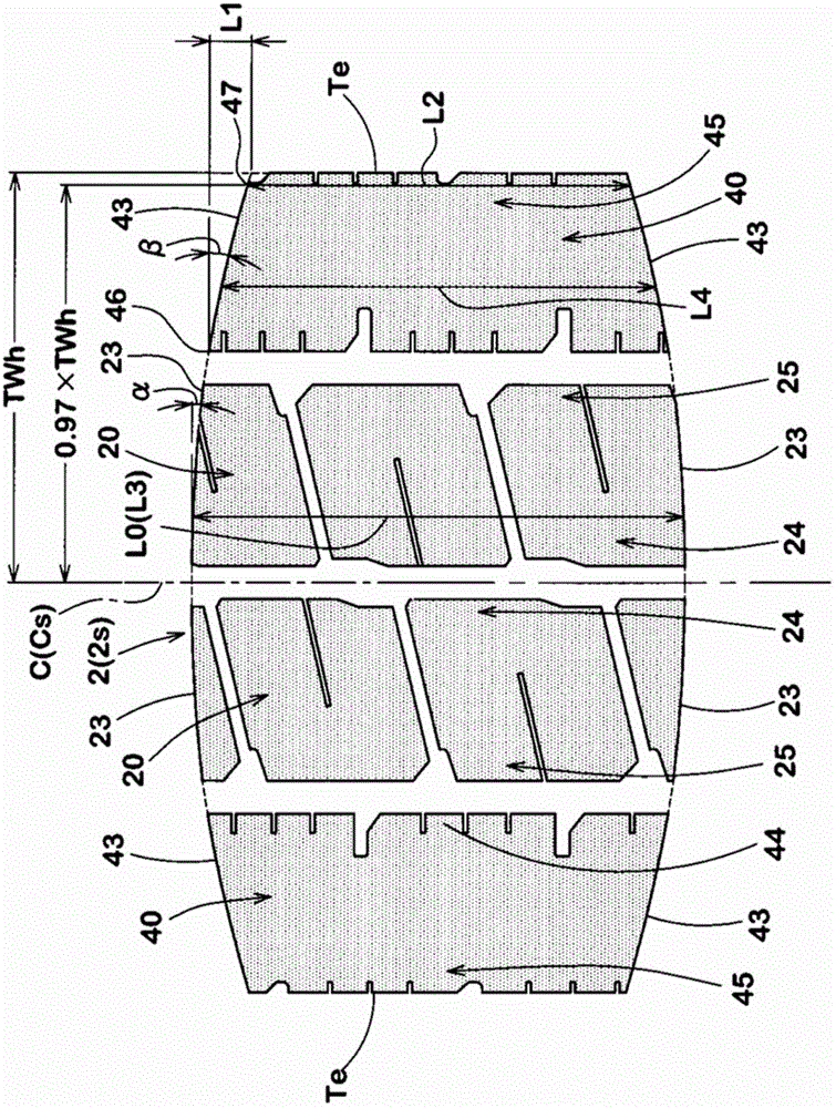
The pneumatic tire provided by the present invention can suppress uneven wear of the tread portion. A pneumatic tire is divided into a pair of shoulder land portions ( 40 ) and a pair of middle land portions ( 20 ) by providing a center main groove ( 9 ) and a pair of shoulder main grooves ( 10 ). Edges ( 23 ) on both sides of the middle land portion ( 20 ) in the tire circumferential direction extend obliquely to the outside of the tire axial direction at an angle α in the range of 5° to 12° relative to the tire axial direction. Edges (43) on both sides in the tire circumferential direction of the shoulder land portion (40) are inclined at an angle β with respect to the tire axial direction, and the angle β is in the range of the above-mentioned angle α to 17°. The tire circumferential distance (L1) between the tire axial inner end (46) and the outer end (47) of the end edge (43) of the shoulder land portion (40) is the tire circumference of the shoulder land portion (40). 0.03 to 0.12 times the grounding length (L2) of the direction.
Description
technical field [0001] The invention relates to a pneumatic tire which improves the shape of the contact surface and improves the partial wear resistance. Background technique [0002] Such as Figure 5 As shown, various types of pneumatic tires have conventionally been proposed that have main grooves a extending continuously in the tire circumferential direction in the vicinity of the tread edge b. Such a pneumatic tire has a problem that so-called shoulder chip wear tends to occur in which the outer end portion d in the tire axial direction of the shoulder land portion c between the main groove a and the tread edge b is worn unevenly. [0003] In response to such a problem, for example, the following Patent Document 1 proposes a pneumatic tire in which the rigidity of each land portion extending in the tire circumferential direction is rationalized by specifying the number of sipes formed in the land portion, thereby suppressing the Partial wear of the land part. However...
Claims
Login to View More Application Information
Patent Timeline
 Patent Type & Authority Patents(China)
IPC IPC(8): B60C11/03B60C9/02
CPCB60C2011/0344B60C11/01B60C11/03B60C11/04B60C11/12
Inventor 津田训
Owner SUMITOMO RUBBER IND LTD