Cast-in-place hollow floor system using steel mesh and inflatable tube combination box for pore-forming

A hollow floor, inflatable tube technology, which is applied to the on-site preparation of floor slabs and building components, and the formwork/formwork/work frame, etc., can solve the problems of lack of floor crack resistance, high buoyancy, and inconvenient transportation and installation.

Inactive Publication Date: 2014-08-06
王本淼
View PDF11 Cites 45 Cited by
  • Summary
  • Abstract
  • Description
  • Claims
  • Application Information

AI Technical Summary

Problems solved by technology

[0006] The purpose of the present invention is to organically combine the advantages of the steel mesh with the performance of the inflatable tube to provide a brand-new hole-forming technology for the cast-in-place hollow floor. It is not only a part of the box body, but also the support body of the steel mesh. The two work together to improve the overall technical level of the filling body, and effectively solve the problems of vertical anti-floating, horizontal displacement, and reinforcement of the floor in the

Method used


Image

  • Cast-in-place hollow floor system using steel mesh and inflatable tube combination box for pore-forming
  • Cast-in-place hollow floor system using steel mesh and inflatable tube combination box for pore-forming
  • Cast-in-place hollow floor system using steel mesh and inflatable tube combination box for pore-forming

Examples


Embodiment Construction

[0025] The invention will be further described below in conjunction with the accompanying drawings.

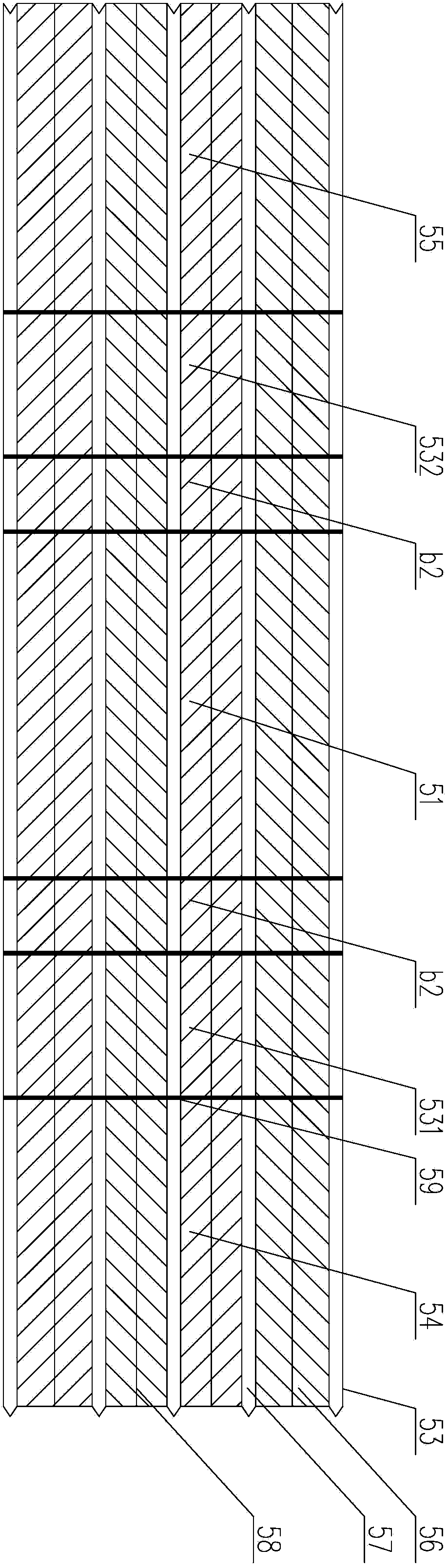
[0026] figure 1 It is a structure diagram of the steel mesh of the steel mesh and the gas-filled tube combined box body of the first embodiment of the present invention. Such as figure 1 As shown, the steel mesh of steel mesh and inflatable tube combination box 5 contains mesh plate 56 and reinforcing rib 57 and connecting plate 58 and side rib 53, and mesh plate 56 and reinforcing rib 57 and connecting plate 58 and side rib 53 form The overall structure of interaction; the steel mesh reinforcement rib 57 is pressed with rows of bending lines 59 in the vertical direction; the steel mesh is determined by the bending lines 59 to make the bottom 51 of the box, and the chord edge b 2 , The box body side wall 531 and the side wall 532, the box top 54 and the box top 55 length.

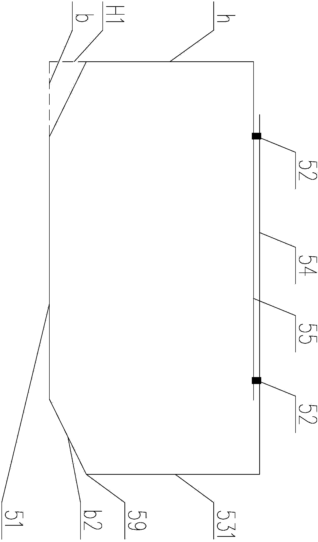
[0027] figure 2 It is a converted cross-sectional view of the steel mesh of the steel mesh and the ...


PUM

PropertyMeasurementUnit
Widthaaaaaaaaaa

Abstract

The invention provides a cast-in-place hollow floor system using a steel mesh and inflatable tube combination box for pore-forming. The cast-in-place hollow floor system is composed of a main beam, a ribbed beam, an upper flange plate, a lower flange plate and the steel mesh and inflatable tube combination box. The main beam is a reinforced concrete combination beam or a fashioned iron beam. The steel mesh and inflatable tube combination box is formed by interacting a steel mesh and inflatable tubes. The steel mesh forms a box top, a box bottom and two side walls of the combination box. According to the inflatable tubes, plastic is made into air storage tubular bodies or polystyrene blocks to form the other two side walls of the steel mesh and inflatable tube combination box and the height of the inner space of the supporting box top and the box bottom. An existing full-sealed hollow filling body and solid filling body are replaced by an unsealed mesh-like box-shaped member for the pore-forming technology of the cast-in-place hollow floor system, and the combination of the steel mesh and the inflatable tubes is adopted. In this way, the problems of plugging of the other two side walls of the steel mesh box and the height of the inner space between the supporting box top and the box bottom are effectively solved, and construction of the cast-in-place hollow floor system is facilitated.

Description

technical field [0001] The invention relates to a cast-in-place hollow floor with holes formed by non-centering filler components, in particular to a cast-in-place hollow floor with holes formed by a combined box body of a steel mesh and an inflatable tube. Background technique [0002] At present, in the technical field of cast-in-place reinforced concrete hollow floors, fully-sealed filler components are usually used to form holes and form hollow floors, such as ZL200410082381.9 "a hollow small ribbed floor" declared by the inventor, which uses thin-walled The box filling body is buried in the small ribbed floor to form a hollow layer with a "T-shaped" stress section, which solves the problem of smooth roof of the "T-shaped" stressed section small ribbed hollow floor, and has been widely used. However, there is no designed stress reinforcement between the bottom of the thin-walled box filling body and the hollow floor formwork, and a layer of crack-resistant steel wire mes...

Claims


Application Information

Patent Timeline
IPC IPC(8): E04B5/32E04G15/06
Inventor 王本淼沈洋王海崴
Owner 王本淼
Why Eureka
Try Eureka