Diesel engine

A diesel engine and injection valve technology, applied in engine components, combustion engines, machines/engines, etc., can solve the problems of decreased air utilization rate and unbalanced fuel distribution, and achieve the effect of reducing soot generation and improving air utilization rate.

Inactive Publication Date: 2014-08-06
MAZDA MOTOR CORP
View PDF8 Cites 6 Cited by
  • Summary
  • Abstract
  • Description
  • Claims
  • Application Information

AI Technical Summary

Problems solved by technology

However, if the injection direction is excessively deviated from the center, the injected fuel from each injector collides with the wall surface of a member such as a piston within a short distance. Higher fuel distribution is still unbalanced, and the air utilization rate is reduced

Method used


Image

  • Diesel engine
  • Diesel engine
  • Diesel engine

Examples


Embodiment Construction

[0023] (1) Li body structure of the engine

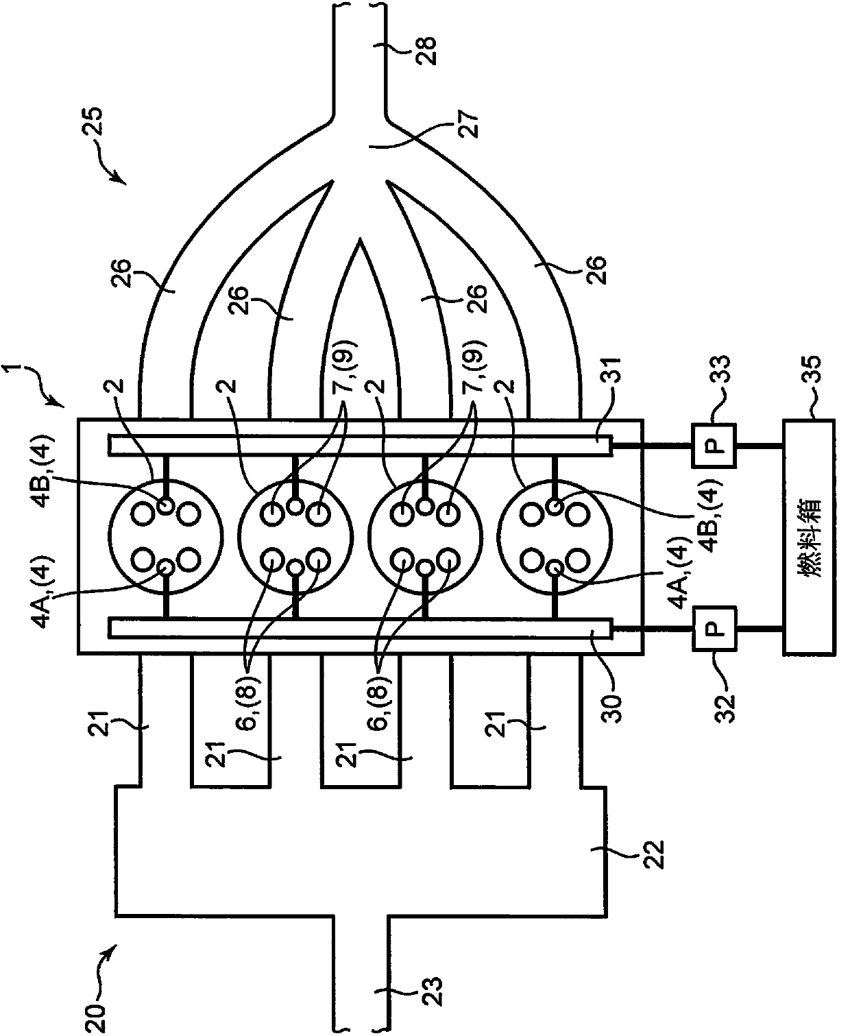
[0024] figure 1 and figure 2 A diesel engine according to one embodiment of the present invention is shown. The diesel engine shown in these figures is a four-cycle multi-cylinder diesel engine mounted on a vehicle as a power source for traveling. Specifically, the diesel engine 2 includes: an inline four-cylinder engine main body 1 having four cylinders 2 arranged in a straight line; an intake passage 20 for introducing air into the engine main body 1; an exhaust passage 25 for Exhaust gas generated by the engine main body 1 is discharged.

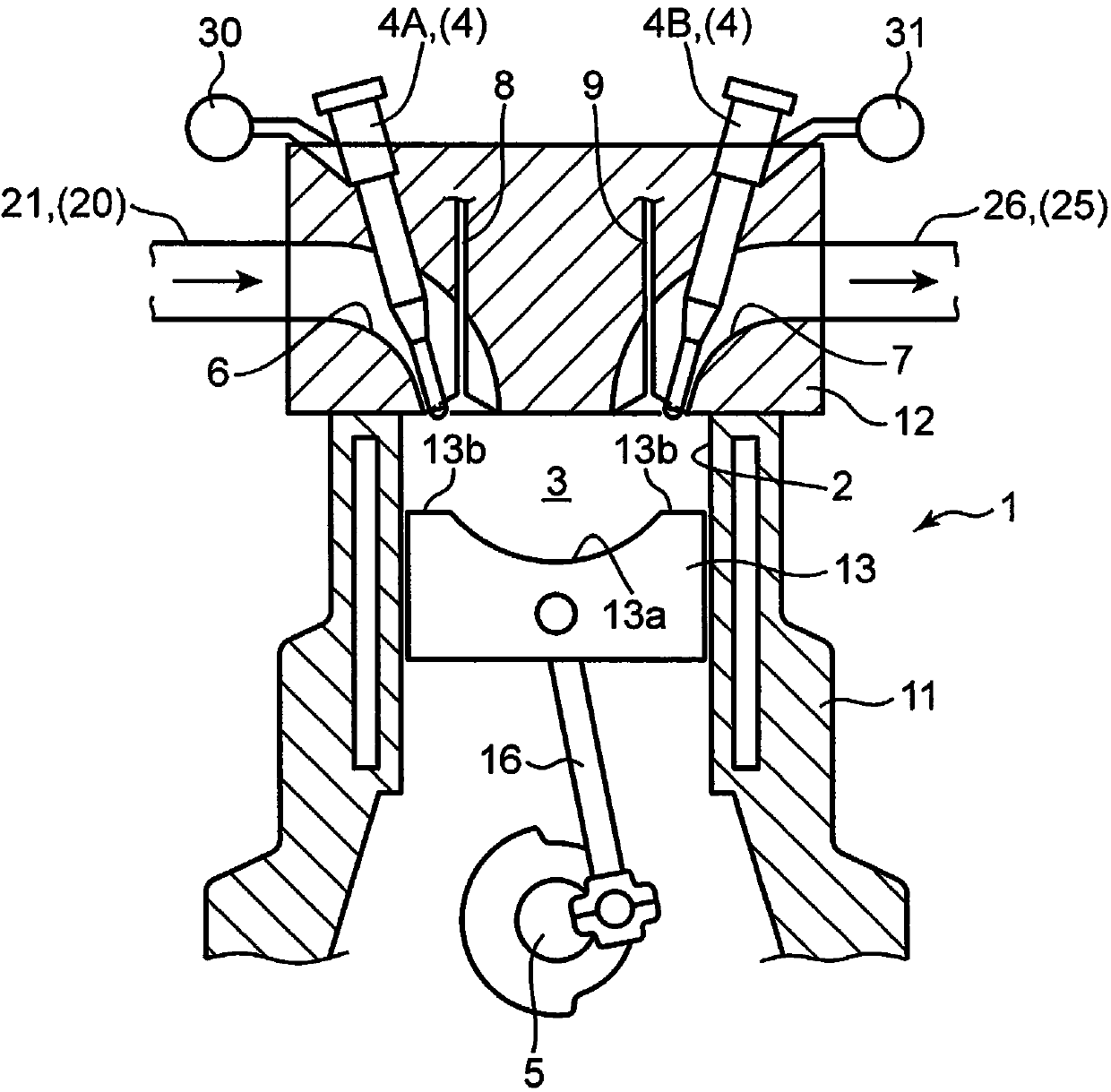
[0025] like figure 2 As shown, the engine main body 1 includes: a cylinder block 11 with the four cylinders 2 formed therein; a cylinder head 12 disposed on the upper surface of the cylinder block 11;

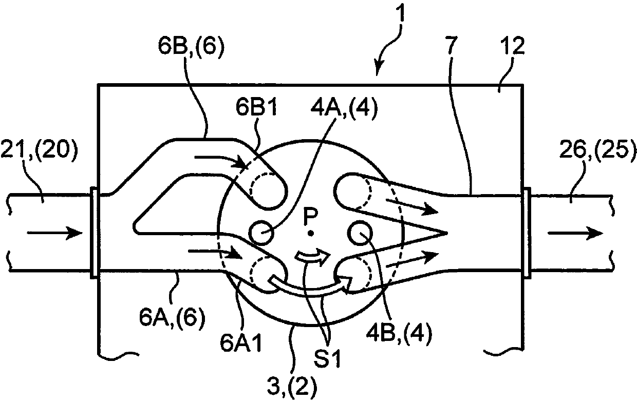
[0026] In each cylinder 2, above the piston 13, a combustion chamber 3 that is circular in plan view is defined and formed. In the combustion chamber 3 , fuel (light oil) injected from a...


PUM


Abstract

The invention relates to a diesel engine. An injector of the diesel engine has a first injection valve and a second injection valve disposed to face each other with respect to the center of a combustion chamber. Assuming that a straight line passing through the first injection valve and the second injection valve is a symmetrical line, one of two regions obtained by dividing a planar region of a combustion chamber (3) into two along the symmetrical line is a first region, and the other of the two regions is a second region, the first injection valve injects fuel toward the first region, and the second injection valve injects fuel toward the second region. A cavity portion is formed in the top surface of a piston. The first injection valve and the second injection valve respectively have injection holes at radially inner positions than the periphery of the cavity portion in plan view. Thus, the utilization rate of air in the combustion chamber can be improved, thereby effectively reducing generation of soot.

Description

technical field [0001] The present invention relates to a diesel engine that diffuses and combusts fuel injected from an injector in a combustion chamber. Background technique [0002] As such a diesel engine, for example, a diesel engine disclosed in Japanese Patent Laid-Open Publication No. 2007-231908 (Patent Document 1) is known. Specifically, the diesel engine of Patent Document 1 is equipped with a pair of side injectors (first side injector and second side injector) capable of directly injecting fuel into the combustion chamber at the edge of the combustion chamber top wall facing the piston top surface. side injectors). [0003] The above-mentioned first and second side injectors are arranged facing each other and facing the center of the combustion chamber. In this state, if the fuel is injected from the injectors at the same time, the injected fuels from the injectors collide with each other, and therefore, atomization of the fuel is promoted by the impact at the...

Claims


Application Information

Patent Timeline
Patent Type & Authority Applications(China)
IPC IPC(8): F02M61/14
CPCF02B23/0621F02B23/0624F02B23/0636F02B23/0663F02B23/0669F02B23/0675F02B31/02F02M61/14F02M61/1813F02M61/182F02M61/1826Y02T10/12
Inventor 饭田晋也金尚奎神崎淳横尾健志
Owner MAZDA MOTOR CORP
Why Eureka
Try Eureka