
An aeration device and biological reaction system suitable for biological desulfurization of natural gas

A technology of aeration device and biological desulfurization, applied in the field of aeration device and biological reaction system, can solve the problems of easy blockage of aeration device, complicated use and maintenance, high investment and cost, and improve air utilization rate and service life. Long, prevent liquid backflow effect

Active Publication Date: 2018-12-25
PETROCHINA CO LTD
View PDF9 Cites 0 Cited by
  • Summary
  • Abstract
  • Description
  • Claims
  • Application Information

AI Technical Summary

Problems solved by technology

However, mechanical aeration is more complicated in design, manufacture, installation, and on-site use and maintenance, with higher investment and cost, and is not widely used.
[0008] In the process of realizing the present invention, the inventors found that there are at least the following problems in the prior art: for the biological desulfurization aeration device, the aeration device is easily blocked

Method used


Image

  • An aeration device and biological reaction system suitable for biological desulfurization of natural gas
  • An aeration device and biological reaction system suitable for biological desulfurization of natural gas
  • An aeration device and biological reaction system suitable for biological desulfurization of natural gas

Examples


Embodiment approach

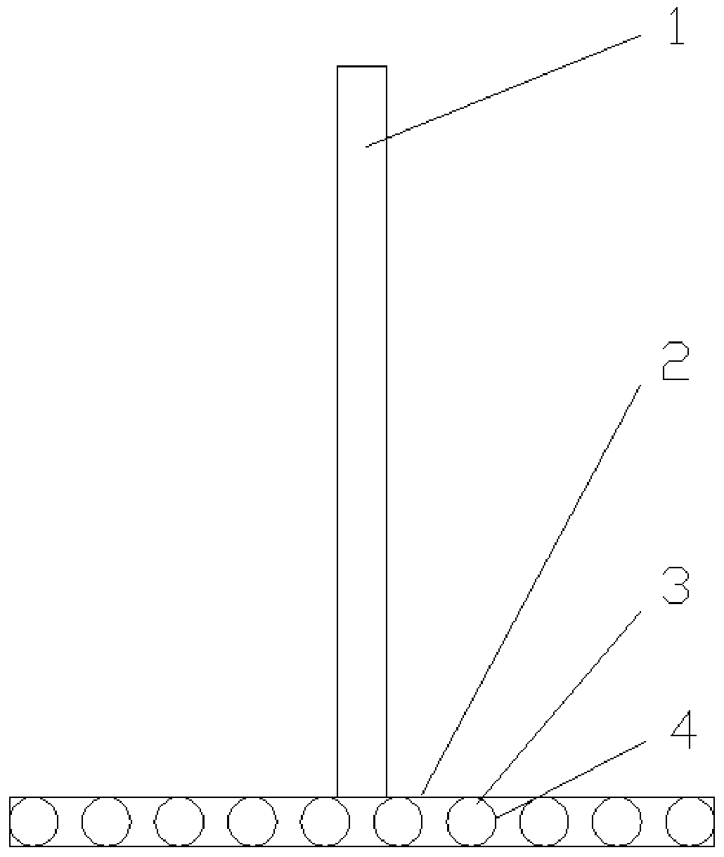
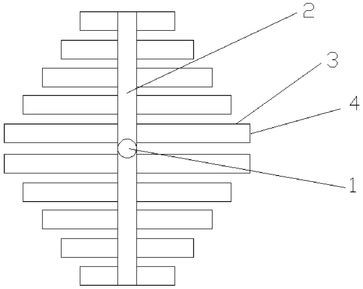
[0047] The first embodiment of the present invention is an aeration device suitable for biological desulfurization of natural gas. like figure 1 , figure 2 as shown, figure 1 It is a schematic structural view of the aeration device in Embodiment 1; figure 2 for figure 1 top view. The device comprises: an air intake main pipe 1, which is used to connect with air supply equipment; a distribution pipe 2 communicated with the air intake main pipe 1, which is perpendicular to the air intake main pipe; a plurality of distribution branch pipes 3 communicated with the distribution pipe, Each distribution branch pipe is perpendicular to the distribution pipe and is in the same plane as the distribution pipe; the elastic aeration membrane 4 wrapped on the distribution pipe has multiple aeration membranes on the elastic aeration membrane 4 The aeration hole is in an open state during aeration, and is in a closed state when there is no aeration or the aeration pressure is insuffici...

Embodiment approach 2

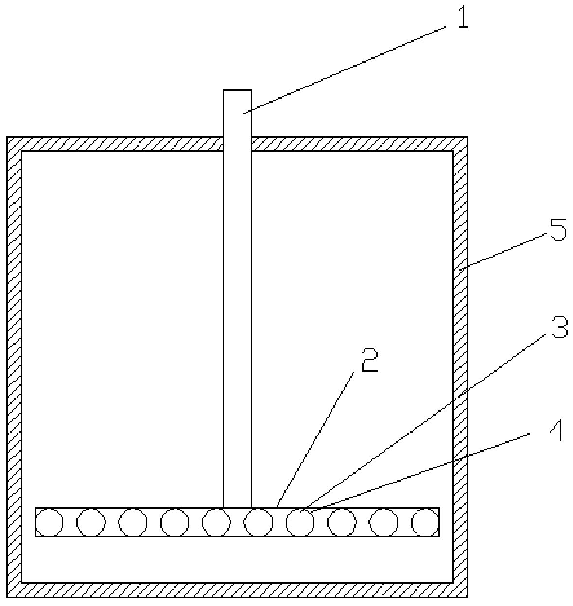
[0062] The second embodiment of the present invention is a biological reaction system suitable for biological desulfurization of natural gas. like image 3 , Figure 4 shown. image 3 It is a structural schematic diagram of the biological reaction system of Embodiment 2, Figure 4 for image 3 top view. The biological reaction system includes a biological reaction tank 5 and the aeration device described in Embodiment 1. The center line of the main air intake pipe 1 of the aeration device is perpendicular to the top plane of the biological reaction tank 5 and runs through the biological reaction tank 5. The center of the top plane of the reaction cell.

[0063] When the biological reaction system is in operation, the desulfurized rich liquid containing hydrogen sulfide enters the biological reaction tank from the upstream unit, and the desulfurized microorganisms regenerate the desulfurized rich liquid by using the air blown in from the aeration device described in Embodi...

Embodiment approach 3

[0069] Figure 5 It is a structural schematic diagram of the aeration device of the third embodiment of the present invention. like Figure 5 As shown, the difference between the third embodiment and the above-mentioned first embodiment is that the shape of the gas distribution pipe 2 is two connected semicircles, that is, the central angle corresponding to the arc is 180°. The central angle of the above-mentioned arc is not limited to 180°, and can be adjusted according to the properties of the desulfurized rich liquid and the demand for sulfur yield. For example, the central angle can also be 150°, 160°, 170°, 190°, 200° °. combine image 3 and Figure 5 It can be seen that the inner diameter of the biological reaction tank 5 is constant, and the use of the arc-shaped distribution pipe 5 can increase the number of distribution branch pipes 3, thereby improving the aeration efficiency. In Embodiment 1, the straight distribution pipe 2 makes the distribution branch pipe 3...


PUM

PropertyMeasurementUnit
pore sizeaaaaaaaaaa
pore sizeaaaaaaaaaa
angleaaaaaaaaaa

Abstract

The invention discloses an aeration device applicable to biological desulfurization of natural gas, and a biological reaction system and belongs to the field of natural-gas purification devices. The aeration device applicable to the biological desulfurization of the natural gas comprises a gas inlet main pipe, a distributing pipe, a plurality of distributing branch pipes and elastic aerating films, wherein the gas inlet main pipe is used for being connected with gas supply equipment; the distributing pipe communicates with the gas inlet main pipe and is vertical to the gas inlet main pipe; the distributing branch pipes communicate with the distributing pipe, and each distributing branch pipe is vertical to the distributing pipe and is located in the same plane where the distributing pipe is located; and the elastic aerating films wrap the distributing branch pipes, a plurality of aerating holes are formed in each elastic aerating film, and the aerating holes of the aeration device are in an open state during aeration and are in a closed state when aeration is not carried out or the aeration pressure is insufficient. The biological reaction system comprises a biological reaction tank and the aeration device which is located inside the biological reaction tank. According to the aeration device applicable to the biological desulfurization of the natural gas, and the biological reaction system, the problem that a gas inlet pipeline is plugged by solid particles in a sulfur-bearing pregnant solution regeneration process of the biological desulfurization of the natural gas can be effectively solved.

Description

technical field [0001] The invention relates to an aeration device and a biological reaction system, in particular to an aeration device and a biological reaction system suitable for natural gas biological desulfurization, and belongs to the field of natural gas purification devices. Background technique [0002] Aeration devices are widely used in various fields such as biological fermentation and sewage treatment. The role of the aeration device in the regeneration process of natural gas biological desulfurization sulfur-containing rich liquid is mainly reflected in the following two aspects: on the one hand, the air is blown into the bioreactor, and the oxygen in the air provides an aerobic environment for the thiobacteria, oxidizing sulfide , to generate elemental sulfur and form a desulfurization effect. The main reaction formula is as follows: [0003] HS – +1 / 2O 2 →S+OH – [0004] HS – +2O 2 → SO 4 2– +H + [0005] On the other hand, air was blown in to st...

Claims


Application Information

Patent Timeline
Patent Type & Authority Patents(China)
IPC IPC(8): C02F3/16C10L3/10B01D53/84B01D53/48
CPCY02A50/20Y02W10/10
Inventor 刘其松徐波何金龙常宏岗孙茹
Owner PETROCHINA CO LTD
Learn More