Centrifugal speed adjustment tail vane deflection yaw type wind generating set

A technology for wind turbines and generators, used in wind turbines, wind turbine control, wind power generation, etc., can solve the problems of poor anti-vibration performance, large losses, easy damage to wind turbines, etc. The effect of reliability

Inactive Publication Date: 2014-08-06
象山众用洁能设备厂
View PDF3 Cites 7 Cited by
  • Summary
  • Abstract
  • Description
  • Claims
  • Application Information

AI Technical Summary

Problems solved by technology

[0006] However, due to the lack of controllable and effective wind-shielding devices in the current micro-sized wind turbine structure, the rotational speed of the wind turbine rotor is directly proportional to the wind speed.
Exceeding the rated wind speed, the speed of the wind rotor of the generator increases exponentially. Once a wind force of level 10 or above occurs, the wind turbine will be damaged to varying degrees due to the excessive speed of the wind rotor, and the loss will be great.
[0007] Especially when using offshore wind energy to generate electricity, the ocean wind conditions are complicated, and winds of grade 10 are common. Ocean-going ships are still operating when winds of grade 9 are used, and wind shelters are used only when winds of grade 10 are above. , it is easy to damage the wind turbine
In the prior art, although there are some generators that can adjust the tail rudder, the angle of the tail rudder can be adjusted when the wind speed exceeds the rated wind speed, but the current technology is mainly adjusted through the connecting rod, and this structure is anti-vibration Poor performance, poor speed limit performance, high failure rate

Method used


Image

  • Centrifugal speed adjustment tail vane deflection yaw type wind generating set
  • Centrifugal speed adjustment tail vane deflection yaw type wind generating set
  • Centrifugal speed adjustment tail vane deflection yaw type wind generating set

Examples


Embodiment Construction

[0028] The present invention will be further described below in conjunction with the accompanying drawings and specific embodiments, but the present invention is not limited to these embodiments.

[0029] The present invention covers any alternatives, modifications, equivalent methods and schemes made on the spirit and scope of the present invention. In order to provide the public with a thorough understanding of the present invention, specific details are set forth in the following preferred embodiments of the present invention, but those skilled in the art can fully understand the present invention without the description of these details.

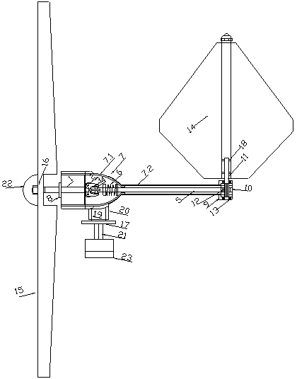
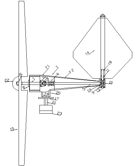
[0030] Such as figure 1 and 2 As shown, the centrifugal speed regulation folding tail yaw type wind power generating set of the present invention comprises a wind wheel, a transmission shaft 1, a tail rudder 14, a tail rudder push-pull rod 5 and a tail rudder mounting frame 9, and the tail rudder 14 is installed on the tail On the rudd...


PUM


Abstract

The invention discloses a centrifugal speed adjustment tail vane deflection yaw type wind generating set. The wind generating set comprises fan blades (15), a transmission shaft (1), a tail vane (14), a tail vane push-pull rod (5) and a tail vane installation rack (9). The tail vane (14) is installed on the tail vane installation rack (9). The fan blades (15) are connected to the front end of the transmission shaft (1) in a rotating mode. The tail vane (14) can rotate under the pushing and pulling effects of the tail vane push-pull rod (5). The wind generating set further comprises a tail vane rotation gear shaft (11). A tail vane push-pull rack (12) matched with the tail vane rotation gear shaft (11) is arranged at the rear end of the tail vane push-pull rod (5). One end of the tail vane rotation gear shaft (11) is fixedly connected with the tail vane (14), and the other end of the tail vane rotation gear shaft (11) is provided with a gear shaft body and is installed on the tail vane installation rack (9) in a rotating mode. The wind generating set is protected and can work normally and generate electricity continuously in strong wind, and the product reliability is improved.

Description

technical field [0001] The invention relates to the field of wind power generation, in particular to a centrifugal speed regulation folding tail yaw type wind power generating set. Background technique [0002] Wind energy is a good renewable and non-polluting resource, especially in the southeast coast of my country where there is a large amount of marine wind energy. Wind power generation is the main form of wind energy utilization. [0003] The working principle of the wind turbine is simply: the kinetic energy of the wind (that is, the kinetic energy of the air) is converted into the kinetic energy of the generator rotor, and the kinetic energy of the rotor is converted into electrical energy. The part that utilizes wind energy and renewable energy, that is, the wind wheel is installed on the shaft of the generator, and the wind wheel cuts the wind speed to generate lift and rotates, driving the generator rotor to rotate and cut the magnetic lines of force to generate e...

Claims


Application Information

Patent Timeline
Patent Type & Authority Applications(China)
IPC IPC(8): F03D7/04
CPCY02E10/72
Inventor 周大川
Owner 象山众用洁能设备厂
Why Eureka
Try Eureka