Electric energy meter correction table and electric energy meter correction method

A technology of electric energy meter and meter calibration table, applied in the direction of measuring electrical variables, measuring devices, instruments, etc., can solve the problems of low adjustment efficiency, increasing the equipment and space required for adjustment, disrupting the rhythm of production lines, etc. The effect of high efficiency, reducing production cost and improving production efficiency

Inactive Publication Date: 2014-08-06
李刚强 +1
View PDF10 Cites 4 Cited by
  • Summary
  • Abstract
  • Description
  • Claims
  • Application Information

AI Technical Summary

Problems solved by technology

[0005] 1. The semi-finished electric energy meter needs to be moved from the production line to the calibration room for setting and calibration. After the adjustment is completed, it must be moved to the production line to complete the follow-up process, which disrupts the rhythm of the production line and increases the workload of transporting semi-finished products. Added equipment and venues required for calibration;
[0006] 2. The adjustment process of the meter calibration cabinet is manually operated, and the adjustment efficiency is low, which increases production personnel and production costs

Method used


Image

  • Electric energy meter correction table and electric energy meter correction method
  • Electric energy meter correction table and electric energy meter correction method
  • Electric energy meter correction table and electric energy meter correction method

Examples


Embodiment Construction

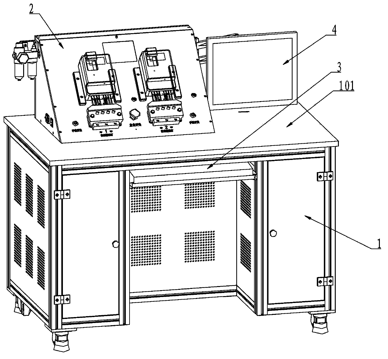
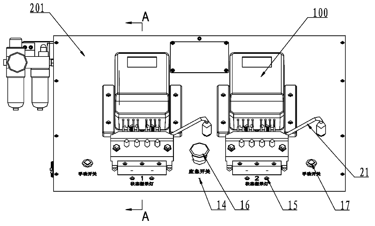
[0031] exist Figure 1 to Figure 10 In the illustrated embodiment of the electric energy meter calibration platform of the present invention, the electric energy meter calibration platform includes a workbench 1 and an operation platform 2 . The console 2 is fixed on the platen 101 of the workbench, and the front of the console 2 is a panel 201 inclined backward by 45°.

[0032] The host 20 of the PC, the power supply 18 (including the power supply circuit of the electric energy meter), and the control board 19 (the control unit composed of the single-chip microcomputer and peripheral circuits) are installed in the cabinet at the bottom of the workbench 1, and the keyboard 3 of the PC is placed on the workbench platen Below 101 , the monitor 4 of the PC is fixed on one side of the console 2 .

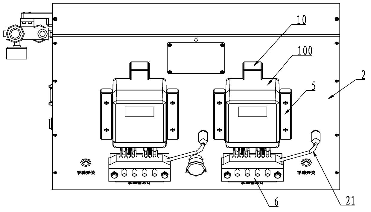
[0033] There are two epitopes 201a on the panel 201, and the two epitopes can be operated simultaneously or separately. Each meter position 201a is equipped with two guide blocks 5 wi...


PUM


Abstract

The invention discloses an electric energy meter correction table and an electric energy meter correction method. The electric energy meter correction table comprises a PC (personal computer), an electric energy meter power supply circuit, a control unit, a surface plate, two guiders, connecting terminal seats and electric energy meter clamping devices, wherein the connecting terminal seats and the electric energy meter clamping devices are mounted on the surface plate. The connecting terminal seats are disposed on the surface plate and below meter positions of electric energy meters to be measured. Each connecting terminal seat comprises a plurality of power source terminal vibrating needles connected with the electric energy meter power supply circuit and a plurality of communication terminal vibrating needles electrically connected with a communication connector of the PC. Each electric energy meter clamping device comprises a press block arranged above the meter positions and driven by an air cylinder. The guiders are arranged on the surface plate and on two sides of the meter positions. The electric energy meter correction table is disposed on a work station of an electric energy meter production line and between an initial assembling work station and a packaging work station of the production line. The electric energy meter correction table is high in correction efficiency, capable of directly setting and correcting electric energy meters on and along with the production line, production efficiency of electric energy meter correction is improved and production cost is reduced.

Description

[technical field] [0001] The invention relates to the adjustment of electric energy meters, in particular to an electric energy meter calibration table and an electric energy meter adjustment method. [Background technique] [0002] The electric energy meter calibration table is used for setting and measuring the parameters of the multi-functional electric energy meter during the production process. In the traditional calibration method, the energy meter is assembled into a semi-finished product and transferred from the production line to the energy meter calibration room for parameter setting and calibration, and then the calibrated energy meter is transferred from the calibration room to the assembly and packaging production line for assembly and packaging. [0003] The meter calibration cabinet in the watt-hour meter calibration room includes the power supply circuit of the watt-hour meter, the control unit, the vertical panel, the wiring terminal block installed on the pa...

Claims


Application Information

Patent Timeline
Patent Type & Authority Applications(China)
IPC IPC(8): G01R35/04
Inventor 李沛霖李刚强
Owner 李刚强
Why Eureka
Try Eureka