Supercharge Your Innovation With Domain-Expert AI Agents!

Lens structure

A lens and lens barrel technology, applied in the field of projection lenses, can solve problems such as inconvenient use, blurred images, and affecting the quality of projectors, and achieve the effect of solving blurring and improving quality

Inactive Publication Date: 2014-08-06
FOSHAN PREMIER SCI & TECH CO LTD +1
View PDF4 Cites 2 Cited by
  • Summary
  • Abstract
  • Description
  • Claims
  • Application Information

AI Technical Summary

Problems solved by technology

During the temperature conduction process of the projection lens, the gas in the closed space between the two lens barrels will be cooled in the front and heated in the back, and this phenomenon will lead to fog on the surface of the last lens of the front group of lenses with a relatively low temperature. , the fog on the lens will make the projected image blurred, and the fog will disappear when the temperature of the front group lens is the same as that of the rear group lens, causing the projector to be blurred for a period of time (about five minutes) at the beginning of use. Inconvenience in use affects the quality of the projector

Method used


Image

  • Lens structure
  • Lens structure
  • Lens structure

Examples


Embodiment Construction

[0012] The present invention will be described in detail below in conjunction with the accompanying drawings.

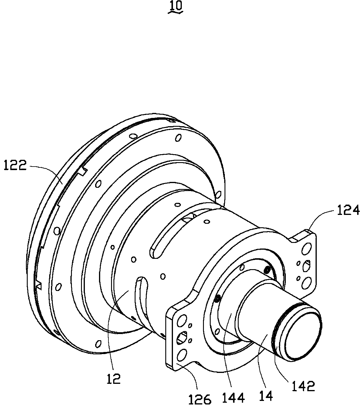
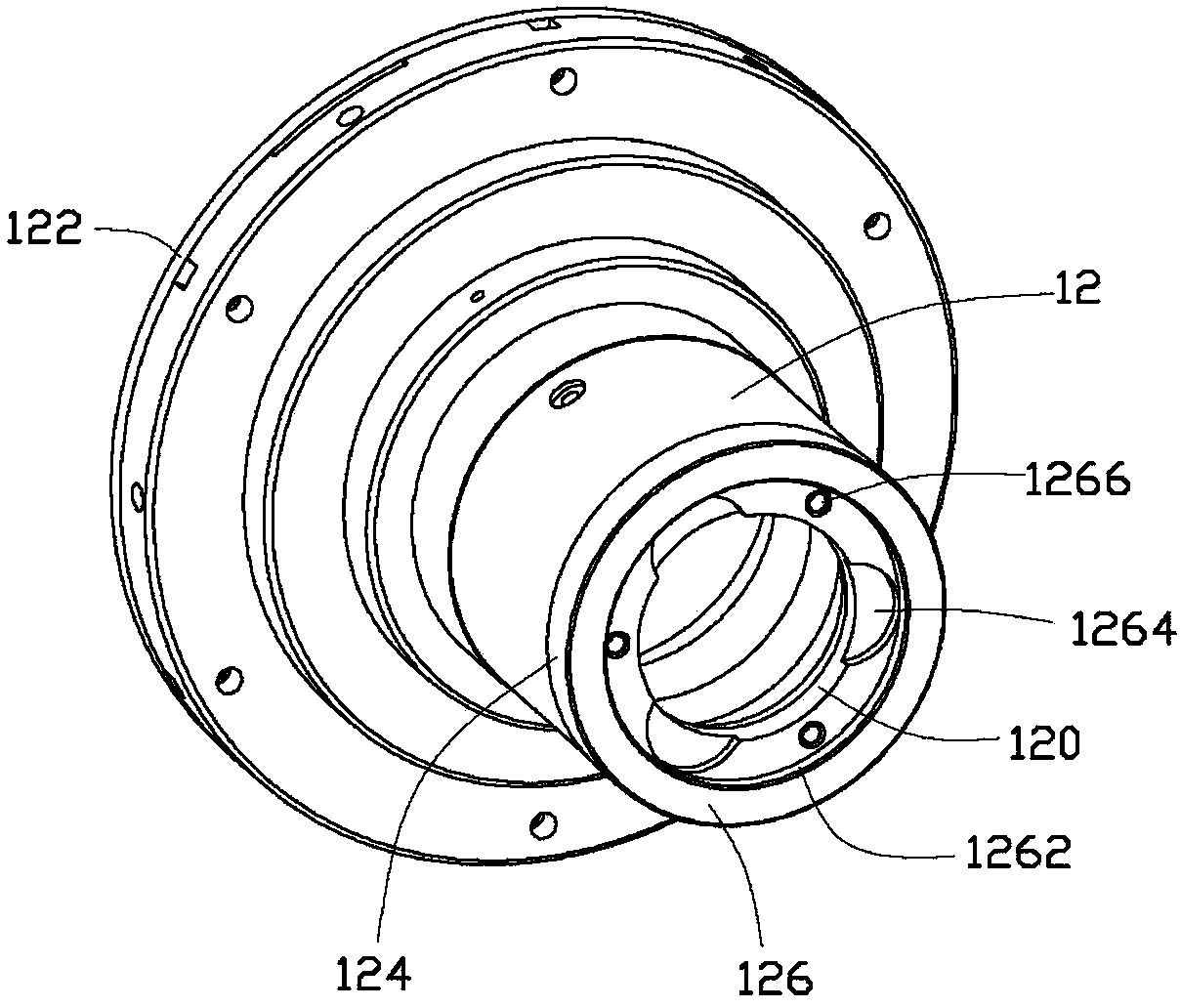
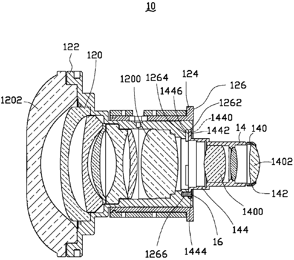
[0013] see figure 1 , is a schematic diagram of an embodiment of the lens structure of the present invention. The lens 10 includes a first lens barrel 12 and a second lens barrel 14 , and the combination of the first lens barrel 12 and the second lens barrel 14 constitutes the lens 10 . The first lens barrel 12 has a projecting end 122 and a carrying end 124, the projecting end 122 and the carrying end 124 are respectively located at two ends of the first lens barrel 12, and the projecting end 122 is used for The image beam is projected out, and the carrying end 124 is used to assemble the second lens barrel 14 . The second lens barrel 14 has a receiving end 142 and a joint end 144, the receiving end 142 and the joint end 144 are respectively located at two ends of the second lens barrel 14, and the receiving end 142 is used to receive The image light beam of the ...


PUM


Abstract

The invention provides a lens structure. The lens structure comprises a first lens cone and a second lens cone. The first lens cone is provided with a bearing plane relative to the second lens cone. The second lens cone is provided with an adjoining plane relative to the first lens cone. The surface of the bearing plane is provided with at least one groove. When the bearing plane is combined with the adjoining plane, the grooves form a vent hole between the first lens cone and the second lens cone. By the vent hole formed by the grooves, the lens can be prevented from generating mist at the early use stage, the good use efficiency is obtained, and the quality of the lens is improved.

Description

technical field [0001] The invention relates to a lens structure, in particular to a projection lens, which can avoid using the lens structure generated by initial fog. Background technique [0002] The projection lens used by the projector usually includes two groups of lenses, the two groups of lenses are respectively assembled in the lens barrel, and the projection lens is formed by the combination of the two lens barrels. At present, the combination of the two lens barrels of the projection lens is connected in a way of direct locking with screws. After the two lens barrels are connected, a closed space is formed between the two lens barrels. When the projection lens matches the light of the projector When the machine light source is used for image projection operation, since the high heat generated by the light source can exceed 80 degrees Celsius, the temperature inside the projector will also increase rapidly. The closer to the light source, the higher the temperature...

Claims


Application Information

Patent Timeline
IPC IPC(8): G02B7/02G03B21/14
Inventor 柳晓娜高晶刘建秋黄海若彭芳英王圣安李安泽林君翰
Owner FOSHAN PREMIER SCI & TECH CO LTD
Features
  • R&D
  • Intellectual Property
  • Life Sciences
  • Materials
  • Tech Scout
  • Unparalleled Data Quality
  • Higher Quality Content
  • 60% Fewer Hallucinations
Learn More