
Memory power supply circuit

A power supply circuit and memory technology, which is applied in the direction of electrical components, static memory, data processing power supply, etc., can solve the problems of reduced memory selection range and inconvenience

Inactive Publication Date: 2014-08-06
HONG FU JIN PRECISION IND (SHENZHEN) CO LTD +1
View PDF0 Cites 0 Cited by
  • Summary
  • Abstract
  • Description
  • Claims
  • Application Information

AI Technical Summary

Problems solved by technology

The current practice can only fix a working voltage of 1.8V or 1.88V. In this case, the selection range of memory will be greatly reduced when assembling the system, which is more inconvenient.

Method used


Image

  • Memory power supply circuit

Examples


Embodiment Construction

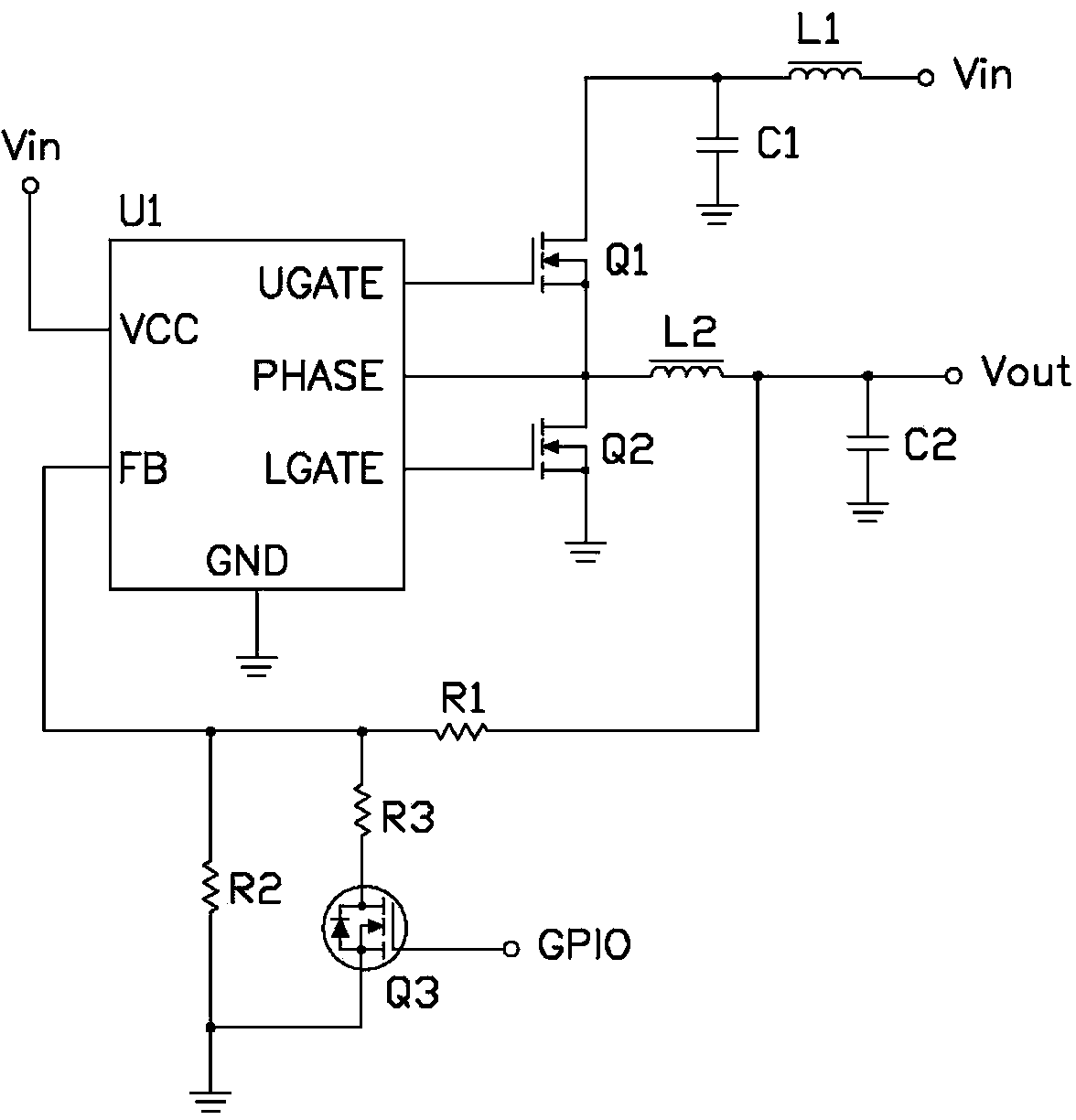
[0010] see figure 1 , the memory power supply circuit of the present invention is used to provide a working voltage for a memory. A preferred implementation of the memory power supply circuit includes a PWM controller U1, field effect transistors Q1-Q3, resistors R1-R3, inductors L1, L2, capacitors C1 and C2.

[0011] The power supply pin VCC of the PWM controller U1 is connected to the voltage source Vin (+5V), the high threshold pin UGATE is connected to the gate of the field effect transistor Q1, and the low threshold pin LGATE is connected to the gate of the field effect transistor Q2. The phase pin PHASE is connected to the source of the field effect transistor Q1 and the drain of the field effect transistor Q2. The drain of the field effect transistor Q1 is connected to the voltage source Vin through the inductor L1, and is also grounded through the capacitor C1. The node between the drain of the field effect transistor Q2 and the source of the field effect transistor ...


PUM


Abstract

The invention discloses a memory power supply circuit which comprises a PWM (Pulse-Width Modulation) controller, a first field effect tube, a second field effect tube, a first resistor, a second resistor, a third resistor, a first inductor, a second inductor and an electronic switch. The memory power supply circuit can adjust a voltage value output to a memory to be first output voltage or second output voltage according to demands.

Description

technical field [0001] The invention relates to a memory power supply circuit. Background technique [0002] In personal computers, the working voltage of memory is generally fixed, such as the working voltage range of DDR2 is 1.8V+ / -0.1V. However, due to the different quality of memory on the market, the optimal operating voltage is also different. For example, the memory of company A can achieve the best performance when operating at 1.8V, and the memory of company B can achieve the best performance when operating at 1.88V. The current practice can only fix a working voltage of 1.8V or 1.88V. In this case, the selection range of memory will be greatly reduced when assembling the system, which is more inconvenient. Contents of the invention [0003] In view of the above situation, it is necessary to provide a memory power supply circuit capable of adjusting the voltage value output to the memory according to requirements. [0004] A memory power supply circuit, comprisi...

Claims


Application Information

Patent Timeline
Patent Type & Authority Applications(China)
IPC IPC(8): G06F1/26
CPCH02M1/44H02M3/156G11C5/14H02M1/0025
Inventor 赖超荣
Owner HONG FU JIN PRECISION IND (SHENZHEN) CO LTD
Learn More