An air duct for accurately supplying air to the side of communication equipment

A technology of communication equipment and precise air supply, applied in the field of air ducts, can solve the problems of waste, poor cooling effect of communication equipment, no cooling of communication equipment, etc., and achieve good cooling effect

Active Publication Date: 2016-05-25
赵威
View PDF3 Cites 0 Cited by
  • Summary
  • Abstract
  • Description
  • Claims
  • Application Information

AI Technical Summary

Problems solved by technology

[0003] The present invention is to solve the problem that the existing heat dissipation method for communication equipment is mainly to use the air conditioning system for refrigeration in a large area in the computer room, and a large part of the cold air produced by the air conditioning system is neutralized by the heat in the surrounding environment. Not all of them are used for cooling communication equipment, resulting in serious waste and poor cooling effect of communication equipment

Method used


Image

  • An air duct for accurately supplying air to the side of communication equipment
  • An air duct for accurately supplying air to the side of communication equipment
  • An air duct for accurately supplying air to the side of communication equipment

Examples


specific Embodiment approach 1

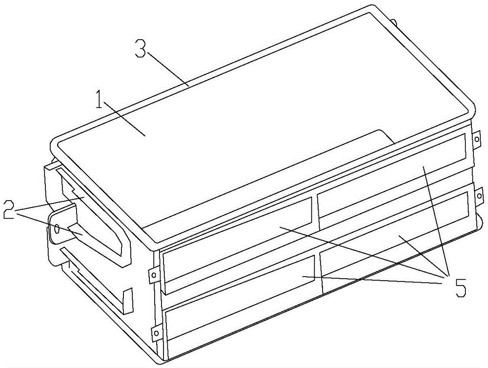
[0036] Specific implementation mode one: see figure 1 Describe this embodiment, the vertical air duct described in this embodiment, which includes: a cylinder, a No. 1 knock-off cover plate 5, a guide chute 2 and a sealing rubber strip 3,

[0037] The cylinder is in the shape of a square cylinder, and the front facade of the cylinder is provided with two groups of horizontally arranged No. 1 knock-off cover plates 5, and each group has two No. 1 knock-off cover plates 5, and the two groups The area covered by the No. 1 knock-off cover plate 5 is the air inlet of the vertical air duct, and each group of No. 1 No. 1 knock-off cover plate 5 is respectively provided with a fixing screw hole on the front facade corresponding to the two ends. Both sides are provided with guide chute 2, the end of the guide chute 2 is provided with fixing screw holes, and the upper edge of the cylinder is fixed with sealing rubber strip 3.

specific Embodiment approach 2

[0038] Embodiment 2: The difference between this embodiment and the vertical air duct described in Embodiment 1 is that the height of the vertical air duct 1 is 2U, where 1U=1.75 inches, and each No. 1 can knock off the cover plate 5 The height is 1U.

specific Embodiment approach 3

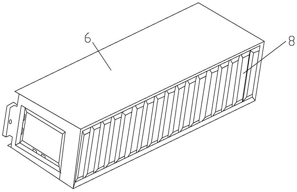
[0039] Specific implementation mode three: see figure 2 Describe this embodiment, the horizontal air duct described in this embodiment, which includes a quadrangular cylindrical cylinder and a plurality of No. 2 knock-off cover plates 8,

[0040] The cross-section of the quadrangular cylinder is rectangular, and the front and rear facades of the quadrangular cylinder are provided with multiple equally spaced No. 2 knock-off cover plates 8, and all knock-off No. The area covered by the knocked-off cover plate 8 is the air inlet of the horizontal air duct 6, and fixing screw holes are provided on both sides of the rear facade of the quadrangular cylinder.


PUM


Abstract

The invention relates to the field of air delivering equipment, in particular to an air duct for accurately and laterally delivering air to communication equipment. The problems that because the using mode of heat dissipation of existing communication equipment is mainly that an air conditioning system is used within a large range for refrigeration in a machine room, a large part of cold air produced by the air conditioning system is neutralized by heat in an ambient environment and not all the cold air is used for refrigerating the communication equipment, waste is severe, and the refrigeration effect of the communication equipment is not good are solved. A perpendicular air duct is in a square tube shape, two sets of knock-off cover plates are horizontally arrayed on the front vertical face, guide sliding grooves are formed in the side faces, and fixing screw holes are formed in the tail ends of the knock-off cover plates. A seal rubber strip is arranged on the upper edge of a tube body. Knock-off cover plates are arranged on the front and the back vertical faces of a horizontal air duct. Fixing screw holes are formed in the two sides of the rear vertical face. A horizontal expanding air duct is provided with the knock-off cover plates of the opposite side walls, fixing screw holes are formed in the side wall of one end large in cross section, and the perpendicular air duct, the horizontal air duct and the horizontal expanding air duct are fixedly connected through penetrating bolts into the corresponding fixing screw holes. The air duct can be used in an equipment cabinet.

Description

technical field [0001] The invention relates to an air duct for supplying air to communication equipment. Background technique [0002] At present, the cooling method used for communication equipment is mainly to use the air-conditioning system for cooling in a large area in the computer room. The communication equipment uses its own chassis fan to directly draw the cold air in the environment of the computer room into the chassis for circulation and heat dissipation. Since most communication equipment is installed in a closed cabinet with front and rear doors, the hot air discharged from the equipment can easily circulate to its own air inlet, forming a small-scale hot air circulation in the cabinet, which is very unfavorable for cooling. At the same time, a large part of the cold air produced by the air conditioning system is neutralized by the heat in the surrounding environment, and not all of it is used to cool the communication equipment. The waste is serious and the ...

Claims


Application Information

Patent Timeline
Patent Type & Authority Patents(China)
IPC IPC(8): H05K7/20
Inventor 赵威
Owner 赵威
Why Eureka
Try Eureka