
Water circulation system for water heater

A water heater and water circulation technology, which is applied to fluid heaters, lighting and heating equipment, etc., can solve the problems of increasing the use of electric energy, waste of water resources, increasing the amount of construction work, failures, troublesome connection of pipelines and circuits, etc. Simple, low heat loss effect

Active Publication Date: 2016-03-02
苏州爱科意智能科技有限公司
View PDF4 Cites 0 Cited by
  • Summary
  • Abstract
  • Description
  • Claims
  • Application Information

AI Technical Summary

Problems solved by technology

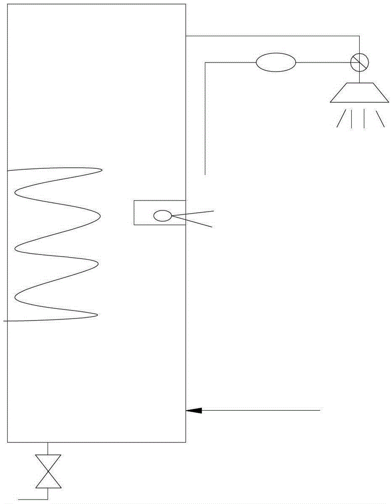
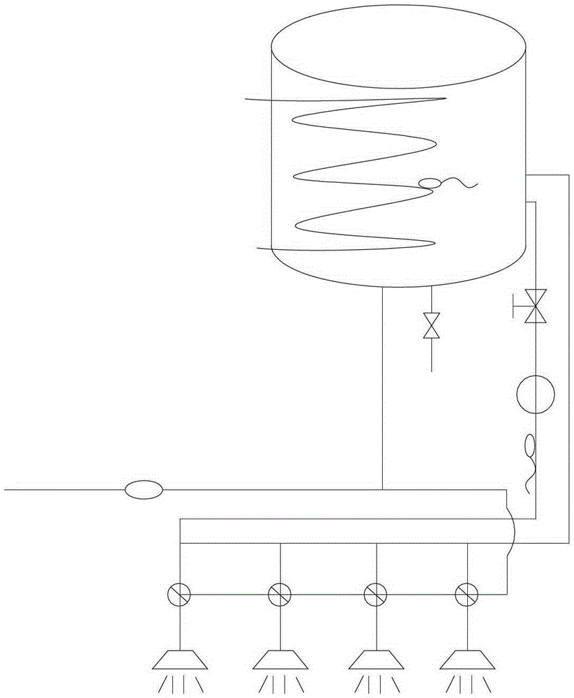
[0003]However, the above two water supply systems have the following problems respectively. Although the pipeline between the outlet of the water heater and the use end is relatively short in the domestic small system, before the hot water comes out Still have to drain the cold water in the pipeline, wasting more water resources, and after the water in the pipeline from the outlet of the water heater to the use end exceeds 20 minutes, the temperature of the water in this section of the pipeline drops to room temperature , re-use also needs to drain the cold water in the pipeline, increasing the use of electricity and the waste of water resources; and the double-pipe connection design adopted in commercial large-scale systems, when hot water is not used, the circulating water pump will be turned on from time to time, Waste of electric energy, and the adoption of circulating water pumps in commercial large-scale systems will undoubtedly bring troubles to pipelines, circuit connections, etc., increasing the construction workload and the possibility of failure during use

Method used


Image

  • Water circulation system for water heater
  • Water circulation system for water heater
  • Water circulation system for water heater

Examples


Embodiment Construction

[0016] The technical solutions of the present invention will be further described below in conjunction with the accompanying drawings and specific embodiments.

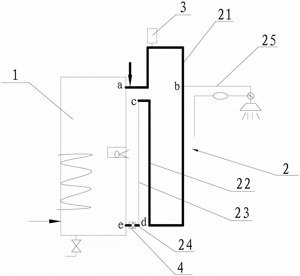
[0017] see image 3 The water heater water circulation system shown includes a water heater 1. The upper end of the water heater 1 has a water outlet, and the lower end of the water heater 1 is provided with a circulating water inlet. The water heater 1 is also provided with an external water supply pipeline (not shown in the figure) to the water heater 1. Make-up port for the water supply in the water tank (not shown). A circulating water pipe 2 is provided between the water outlet and the circulating water inlet, and the circulating water pipe 2 includes successively connected outlet pipe sections 21 ( image 3 Middle ab section), circulation pipe section 22 ( image 3 Middle bc section), pressure pipe section 23 ( image 3 Middle cd section) and inlet pipe section 24 ( image 3 Middle de section), the a...


PUM


Abstract

The invention discloses A water circulation system for a water heater, wherein a circulating water inlet is provided at the lower end of the water heater, and a circulating water pipe is provided between the water outlet of the water heater and the circulating water inlet, and the circulating water pipe is divided into successively connected outlet pipe sections, circulation pipe sections, pressure The pipe section and the water inlet pipe section, in which the insulation layer is set on the outer circumference of the water outlet pipe section, the circulation pipe section and the water inlet pipe section, and there is a height difference between the two ends of the pressure pipe section. When hot water is not used, the water outlet pipe section Under the action of gravity, the water flows back to the water tank of the water heater along the circulation pipe section, the pressure pipe section and the water inlet pipe section, so that it can be heated together with the water in the water heater tank and then output, so as to ensure that the water in the water circulation pipe will not be wasted. , save water resources, and can ensure that the output is always hot water. In the process of water circulation, the heat loss of water is small, which saves a lot of energy. The water circulation system of the water heater has a simple structure and is convenient to use.

Description

technical field [0001] The invention relates to a water circulation system for a water heater, Background technique [0002] At present, the water supply system of water heater products on the market mainly has two structures, one is a small household water supply system, such as the attached figure 1 As shown, it usually uses a single-pipeline water supply, and the water heater outlet and the use end are connected by a single-pipeline; the other is a commercial large-scale water supply system, as shown in the attached figure 2 As shown, the dual-pipeline water supply is adopted, and the water outlet of the water heater is connected to the use end with a double-pipeline, and a circulating water pump is added. When the temperature of the water in the pipeline is lower than the set value, the circulating water pump is turned on to increase the temperature of the water in the pipeline, and the user can have hot water supply in a short time when using it, reducing the loss of ...

Claims


Application Information

Patent Timeline
Patent Type & Authority Patents(China)
IPC IPC(8): F24H9/12
Inventor 王凯
Owner 苏州爱科意智能科技有限公司
Learn More