
Forming method of composite conical shell with end frame

A composite material and strip-end technology, which is applied in the field of composite conical shell molding, can solve problems such as insufficient fiber strength, prepreg wrinkling, and fiber continuity damage, so as to optimize local mechanical properties and improve load bearing efficiency effect

Active Publication Date: 2016-03-30
AEROSPACE RES INST OF MATERIAL & PROCESSING TECH +1
View PDF5 Cites 0 Cited by
  • Summary
  • Abstract
  • Description
  • Claims
  • Application Information

AI Technical Summary

Problems solved by technology

[0006] (1) For the curved surface structure, it cannot be expanded into a plane, and the prepreg blanking can only be approximated by the plane structure. When the prepreg is laid on a curved surface, there must be quality problems such as prepreg wrinkling and overlapping, which will affect the product. Mechanical properties and bearing capacity
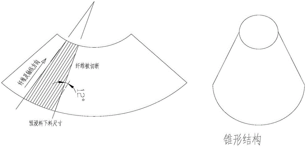
[0007] (2) For the tapered structure, it can be expanded into a plane, but when the prepreg is unloaded, it needs to be divided into blocks, so that some fibers are cut off. The more the prepreg is divided into blocks, the more the fibers are cut, and the fibers are destroyed. continuity, so that the strength of the fiber cannot be fully exerted
[0008] (3) For the tapered structure, due to the different diameters of the upper and lower sections, the manual layup process is adopted, and the layup angle of the prepreg tape cannot be guaranteed

Method used


Image

  • Forming method of composite conical shell with end frame
  • Forming method of composite conical shell with end frame
  • Forming method of composite conical shell with end frame

Examples


Embodiment

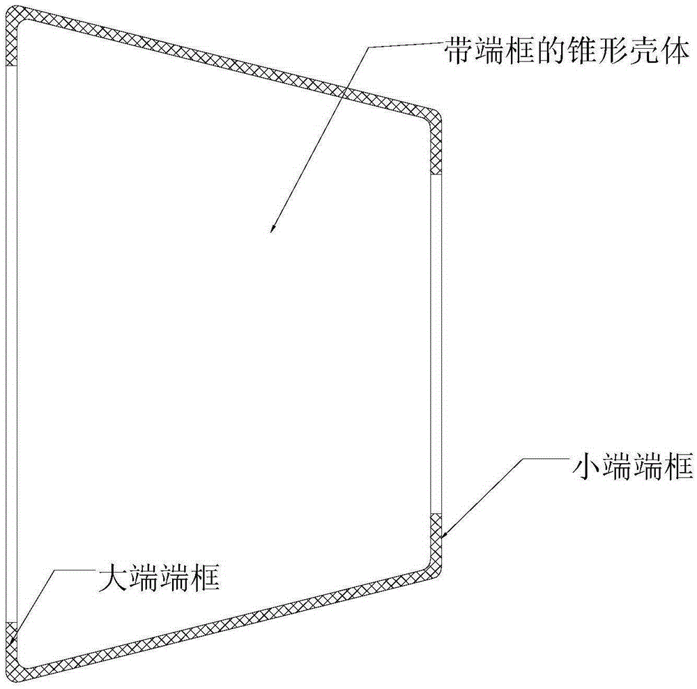
[0033] A composite conical shell with an end frame, the shell has an end frame turned 90° at the end of the shell, which are respectively a small end end frame and a large end end frame.

[0034] A method for preparing a composite conical shell with an end frame, the steps are:

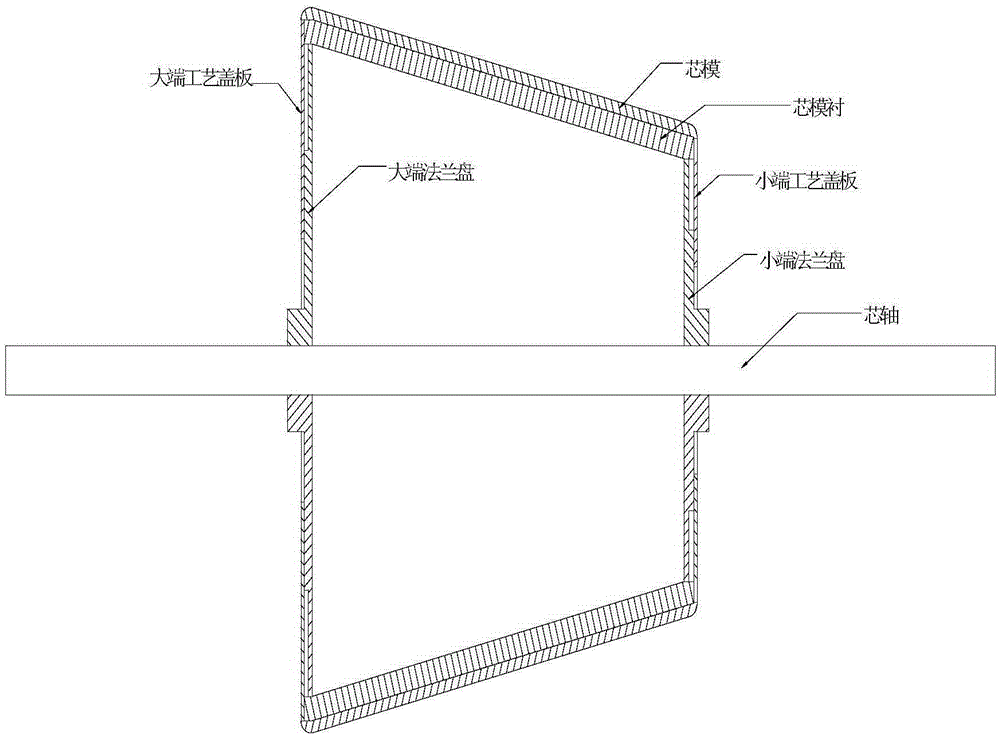
[0035] (1) The forming mold of the shell is prepared by the positive mold forming method: as figure 2 As shown, the mold is composed of a mandrel, a large end flange, a small end flange, a large end process cover plate, a small end process cover plate, a mandrel lining and a mandrel; wherein, the small end of the mandrel lining passes through the small end The end flange is fixed on the mandrel, the small end process cover plate is fixedly connected to the small end flange, and the mandrel is fixedly connected to the outside of the mandrel lining;

[0036] The big end of the mandrel lining is fixed on the mandrel through the big end flange, and the big end process cover plate is fixedly connected to...


PUM

PropertyMeasurementUnit
thicknessaaaaaaaaaa

Abstract

The invention relates to a method for forming a composite conical shell with an end frame and belongs to the field of composite forming technologies. The method comprises the following steps: paving the outer side of the end frame at the small end with composite material pre-impregnation filaments through a manner of automatically paving the filaments and forming, and compacting the composite pre-impregnation filaments; releasing a pressing roller from the surface of a forming die at a corner between the end frame at the small end and a core die, and dryly winding and forming the composite material pre-impregnation filaments by using tension of a filament paving head; then paving the outer side of the core die with the composite pre-impregnation filaments through the manner of automatically paving the filaments and forming, and compacting the composite pre-impregnation filaments; releasing the pressing roller from the surface of the forming die at a corner between the core die and an end frame at the large end, and dryly winding and forming the composite pre-impregnation filaments by using tension of the filament paving head; and then paving the outer side of the end frame of the large end with the composite pre-impregnation filaments through the manner of automatically paving the filaments and forming, and compacting the composite pre-impregnation filaments.

Description

technical field [0001] The invention relates to a molding method of a composite material conical shell with an end frame, belonging to the technical field of composite material molding. Background technique [0002] Foreign countries have widely used automatic molding technology in composite skin component products, which is typically represented by automatic wire laying technology. The automatic wire laying technology is to use a multi-axis laying head (robot) to collect several prepregs into a ribbon under the pressure roller according to the laying direction determined by the design requirements, and then lay it on the surface of the mandrel for compaction and shaping. The whole process is completed by computer measurement, control and coordination system. [0003] The automatic wire laying technology combines the advantages of fiber winding and automatic tape laying technology. It can cut the tow at any time according to the change of the surface shape of the component,...

Claims


Application Information

Patent Timeline
Patent Type & Authority Patents(China)
IPC IPC(8): B29C70/38
CPCB29C70/382
Inventor 张建宝王俊锋刘伟赵文宇张蕾林松孙文文范佳
Owner AEROSPACE RES INST OF MATERIAL & PROCESSING TECH
Learn More