Cable pay-off device

A technology of pay-off device and cable, applied in the directions of transportation and packaging, thin material handling, transportation of filamentous materials, etc., can solve the problems of high consumption, uneven force, damage to the lifting unit, etc., and prolong the service life. , The effect of reducing left and right shaking and uniform force

Inactive Publication Date: 2014-08-13
STATE GRID CORP OF CHINA +3
View PDF9 Cites 11 Cited by
  • Summary
  • Abstract
  • Description
  • Claims
  • Application Information

AI Technical Summary

Problems solved by technology

[0004]1) When lifting the reel 1′ (the cable is wound on the surface), the reel 1′ and the cable are heavy and consume a lot of energy. Turning the left nut 52' and the right nut 62' by force, the labor intensity is relatively large;
[0005]2) After lifting the reel 1′ (the cable is wound on the surface), it is difficult to ensure that the left and right sides of the reel 1′ are separated from the ground by the same distance , that is to say, there is a possibility that one end of the lifting bar 4' is higher and the other end is lower, which directly causes the reel 1' to move to the lower end and damages the lifting unit located at the lower end of the lifting bar 4';
[0006]3) When paying off, the reel 12' rotates around the lifting bar 4', but the reel 12' and the lifting bar 4' are clearance fit, which inevitably makes the reel 1' It is easy to shake left and right along the extension direction of the lifting bar 4', resulting in uneven stress on the left and right lifting units 5', 6', and damaging the left and right lifting units 5', 6';
[0007]4) When paying off the line, the lifting bar 4' cannot be rotated. When the reel 12' rotates too fast, it is easy to cause the lifting bar 4' to contact the reel 12' The deformation of the part makes the service life of the lifting bar 4' relatively low

Method used


Image

  • Cable pay-off device
  • Cable pay-off device
  • Cable pay-off device

Examples


Embodiment Construction

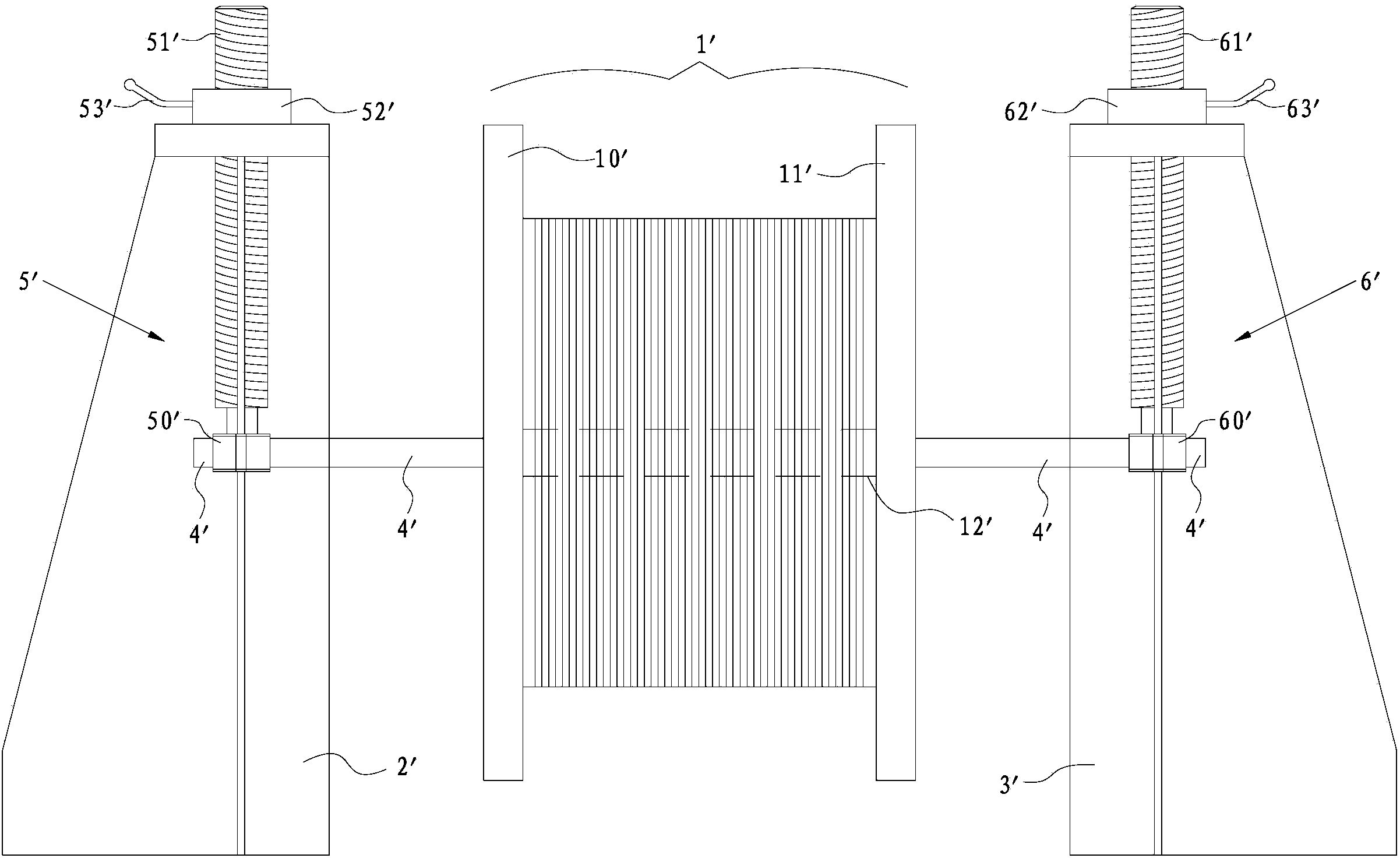
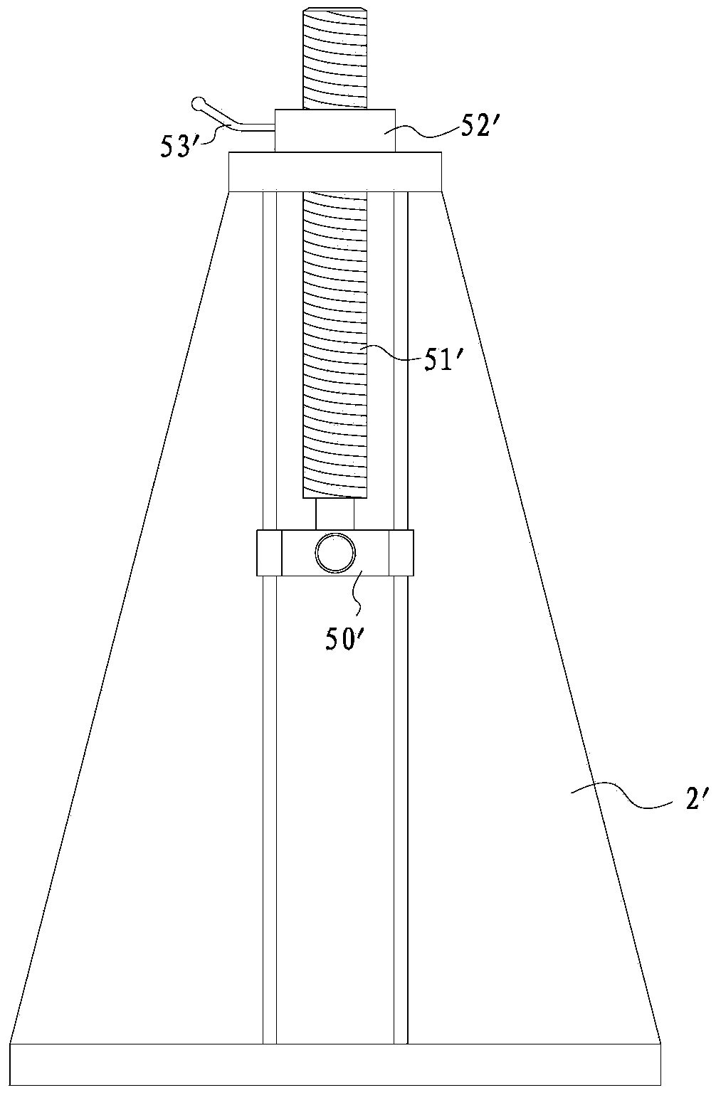
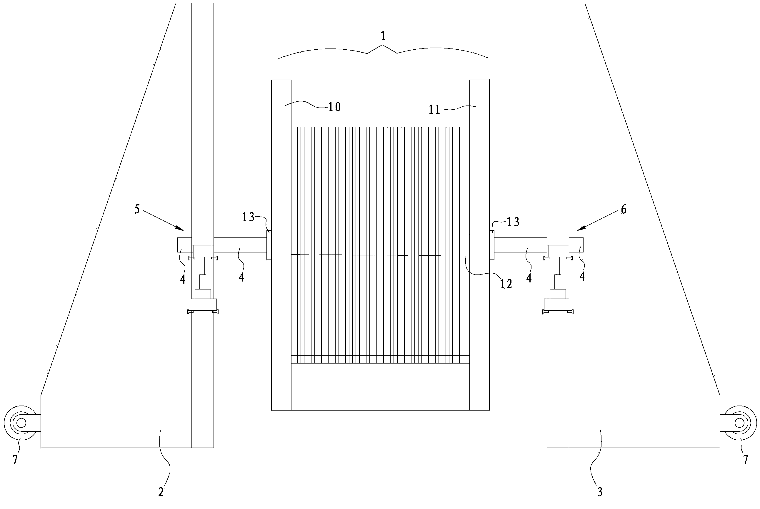
[0035] Such as Figure 3 to Figure 5 As shown, the pay-off device of the present embodiment mainly includes a left pay-off frame 2 and a right pay-off frame 3 located on the left and right sides of the reel 1, a reel shaft 12 crossing the reel 1, and two ends are respectively arranged on the left and right sides of the reel 1. The lifting rod 4 on the pay-off frame 2 and the right pay-off frame 3, and the left lifting unit 5 and Right lift unit 6.

[0036] Wherein the reel 1 comprises a reel 12, a left guardrail ring 10 and a right guardrail ring 11 positioned at both sides of the reel 12, the lifting bar 4 passes through the reel 12, and the reel is locked in the middle part of the lifting bar 4 by using the sleeve 13, so that the reel 12 The center line is collinear with the center line of the lifting bar 4, which effectively reduces the left and right shaking of the reel 1.

[0037] The left pay-off frame 2 and the right pay-off frame 3 are set symmetrically about t...


PUM


Abstract

The invention relates to a cable pay-off device. The cable pay-off device comprises a left pay-off rack, a right pay-off rack, a lifting lever, a left lifting unit and a right lifting unit, wherein the left lifting unit and the right lifting unit lift the lifting lever to enable the lifting lever to rise and fall. Particularly, a reel can be locked on the lifting lever; the left lifting unit comprises two left locating rods, a first sliding base, a second sliding base, a left driving mechanism and a left locating mechanism, wherein the two left locating rods are arranged in parallel in the height direction of the left pay-off rack, the first sliding base and the second sliding base are sequentially and movably arranged between the two left locating rods in the height direction of the left locating rods, the left driving mechanism is arranged on the second sliding base and can conduct lifting adjustment on the first sliding base relative to the second sliding base and the left locating mechanism is used for limiting the second sliding base on the left locating rods. The two ends of the lifting lever are arranged on the left lifting unit and the right lifting unit respectively in a rotating mode. The pay-off device enables the center line of the reel and the center line of the lifting lever to be arranged in parallel, meanwhile, the reel can reduce left-and-right swing of a winding drum during pay-off, therefore, stress borne by the left lifting unit and the right lifting unit is even and deformation of the lifting lever is effectively reduced.

Description

Technical field [0001] The invention is the field of electrical equipment, which involves a line device that specializes in a cable. Background technique [0002] As we all know, after the cable is produced, it is basically rolled on the roll, and then the roll (cable) is transported to a location that needs to be installed or replaced.Put the line, such as figure 1 The launch device shown includes the left and right guardrails 10 ′, 11 ′ on both sides of the rolling tube 1 ′, and the left -folding rack 2 ′ and the right placing rack 3 ′, which is located on the left stitch 2 ′Between the scroll 12 ′ between the rolling tube 1 ′ between the right and right stitch frame 3 ′, and the setting of the bars 4 ′ on the left stitch 2 ′ and the right stitch 3 ′ respectivelyThe left and right ends lift up the left -lift unit 5 ′ and the left lift unit 6 ′. figure 2 ) Including the left connection seat 50 ′ through the confession bars 4 ′, the fixed connection is connected on the left conne...

Claims


Application Information

Patent Timeline
Patent Type & Authority Applications(China)
IPC IPC(8): B65H49/32B65H49/36
Inventor 余力奚若欧李建新
Owner STATE GRID CORP OF CHINA
Why Eureka
Try Eureka