Pipe arc opening machine
A technology for pipelines and outer walls of pipelines, which is applied in the field of pipeline slotting equipment, which can solve the problems of insufficient bearing capacity, reduced pipeline stability, and difficult artificial processing, etc., and achieve the effects of enhanced supporting force, easy entry into the soil, and labor intensity saving for workers
- Summary
- Abstract
- Description
- Claims
- Application Information
AI Technical Summary
Problems solved by technology
Method used
Image
Examples
Embodiment 1
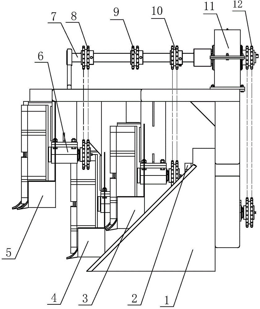
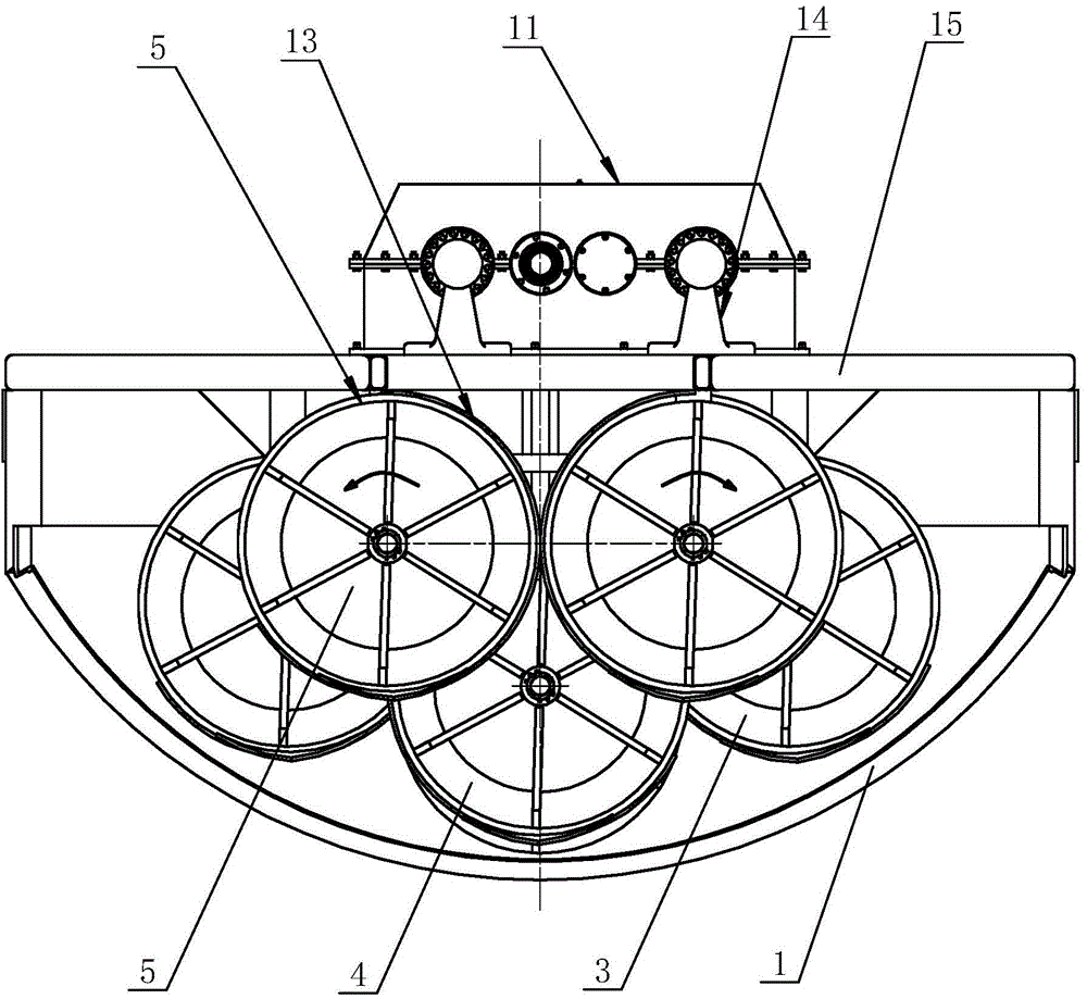
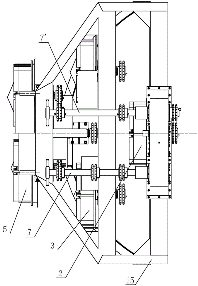
[0036] Embodiment 1: as Figure 1-Figure 3 As shown, the present invention comprises a speed reducer 11, a frame 15 and its upper connection transmission mechanism, a molding die 1, and at least three soil throwing wheels; end, the other soil throwing wheel is a deep soil throwing wheel 4, which is arranged in the rear row of the two front soil throwing wheels 5, and is positioned at the middle and lower position of the two front soil throwing wheels 5. Corresponding to the outer wall of the pipeline, each soil throwing wheel is connected to the reducer 11 through the transmission mechanism, and the forming mold 1 is set on the frame 15 behind the deep soil throwing wheel 4, and the front end of the forming mold 1 is placed on the deep soil throwing wheel 4 In the middle and lower part, the outer arc wall of the molding die 1 is matched with the outer wall of the pipe to be placed. During work, speed reducer 11 is driven by power machine, and the rotation direction of two fro...
Embodiment 2
[0041] Embodiment 2: The difference between this embodiment and Embodiment 1 is that when it is necessary to open a larger arc groove and install a large-diameter pipeline, a set is also provided between the rear column of the depth throwing wheel 4 and the forming die on the frame 15. There are two side by side symmetrical width throwing wheels 3. The width throwing wheel 3 and the front throwing wheel 5 and the depth throwing wheel 4 have the same structure; the arc formed by the two front throwing wheels, the depth throwing wheel and the outer circumference of the two width throwing wheels corresponds to the outer wall of the pipeline to be placed .
[0042]The angle α of the soil throwing sheet and the cone surface of the soil dividing plate in the throwing wheel described in this example is 80 °. The conical fan-shaped arc plate of the soil shovel blade 132 and the soil throwing cover 13 are arranged at an inclined angle, and the angle β between the bottom surface and th...
Embodiment 3
[0043] Embodiment 3: The difference between this embodiment and Embodiment 1 is that a rear earth throwing wheel 2 is provided at the other end of the frame 15 . The soil throwing wheel 2 removes the soil throwing cover 13 on the basis of other earth throwing wheels. Such as Figure 4 Shown, comprise rotating shaft 6, rear plate, soil dividing plate 27 and a plurality of throwing soil pieces 24 that are arranged in pairs, a plurality of throwing soil pieces 24 are evenly arranged on the back plate along the shaft sleeve 23 circumference of rotating shaft, adjacent two throwing soil There are soil-dividing boards 27 connected between the sheets 24, forming a frustum-shaped soil-dividing board as a whole. The soil-throwing sheet 24 is inclined to the conical surface of the soil-distributing plate 27, and the angle α between the soil-throwing sheet 24 and the conical surface of the soil-dividing plate 27 is 80-83°. The ends of the soil throwing tablets 24 are respectively blade...
PUM
 Abstract
Description
Claims
Application Information
 - R&D
- Intellectual Property
- Life Sciences
- Materials
- Tech Scout
- Unparalleled Data Quality
- Higher Quality Content
- 60% Fewer Hallucinations
Browse by: Latest US Patents, China's latest patents, Technical Efficacy Thesaurus, Application Domain, Technology Topic, Popular Technical Reports.
© 2025 PatSnap. All rights reserved.Legal|Privacy policy|Modern Slavery Act Transparency Statement|Sitemap|About US| Contact US: help@patsnap.com


