Wireless positioning method and system based on antenna array phase difference direction-finding radio frequency identification (RFID)

An antenna array and wireless positioning technology, applied in the field of wireless positioning, can solve problems such as interference, adding RFID readers, high complexity and cost

Inactive Publication Date: 2014-08-13
范志广
View PDF5 Cites 59 Cited by
  • Summary
  • Abstract
  • Description
  • Claims
  • Application Information

AI Technical Summary

Problems solved by technology

The existing RFID wireless positioning system mainly has four working principles. The first is based on the positioning of the reader base station. The positioning system is equipped with multiple RFID readers as the positioning base station. By judging which RFID readers the RFID tag to be located is located Within the range, the base station can be approached according to the position of the RFID reader. Although the system is easy to implement at the technical level, the positioning accuracy is low. To improve the positioning accuracy, the number of RFID readers needs to be greatly increased, so the system construction cost and layout complexity are very high; The second is based on received signal strength (RSSI) positioning. The RFID reader estimates the distance from the RFID tag to the RFID reader by detecting the strength of the backscattered signal of the RFID tag, and then performs triangulation calculations based on the distance measurement results of multiple RFID readers. To achieve positioning, the system structure is simple and does not require a large number of RFID readers, but because the RF signal strength is affected by factors such as complex propagation environment and multipath fading, there are disadvantages of low positioning accuracy, and it is easily interfered by other wireless communication systems; The three are based on sending...

Method used


Image

  • Wireless positioning method and system based on antenna array phase difference direction-finding radio frequency identification (RFID)
  • Wireless positioning method and system based on antenna array phase difference direction-finding radio frequency identification (RFID)
  • Wireless positioning method and system based on antenna array phase difference direction-finding radio frequency identification (RFID)

Examples


Embodiment Construction

[0039] With reference to the attached schematic diagram, for an example of a wireless positioning system using dual RFID readers to implement radio frequency identification based on antenna array phase difference and direction finding, the present invention will be further described in detail below.

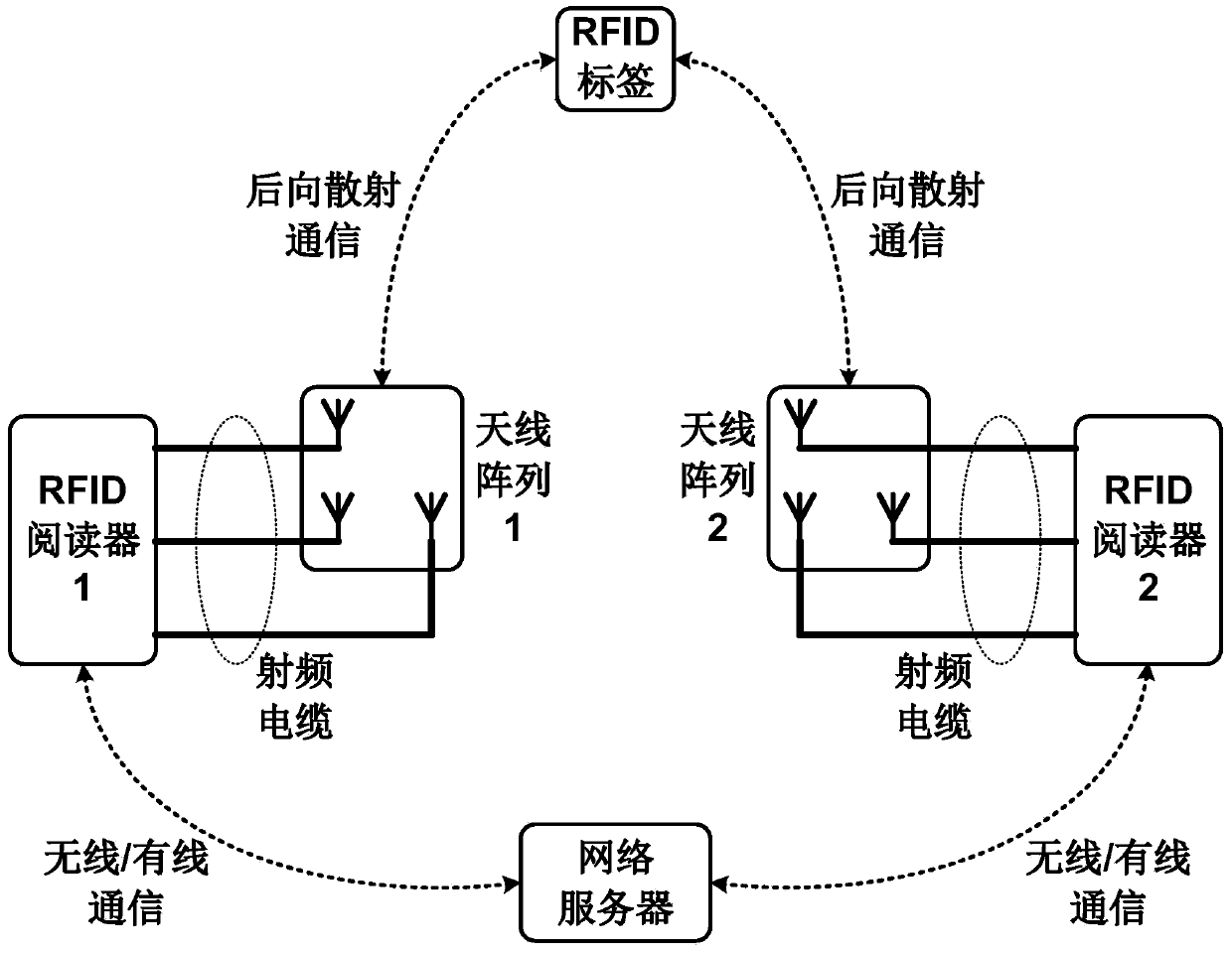
[0040] Such as figure 1 As shown, the components of the wireless positioning system of the present invention include: 1. RFID reader; 2. antenna array; 3. radio frequency cable; 4. RFID tag; 5. network server. The system uses two RFID readers, that is, RFID reader 1 and RFID reader 2, which can perform both double-reader cross-direction-finding positioning and single-reader direction-finding and distance-finding positioning. The system uses two antenna arrays, that is, antenna array 1 and antenna array 2, which work with RFID reader 1 and RFID reader 2 respectively. The antenna array is connected to the reader through multiple radio frequency cables to transmit radio frequency si...


PUM


Abstract

The invention discloses a wireless positioning method and system based on antenna array phase difference direction-finding radio frequency identification (RFID). An antenna array is configured for an RFID reader and comprises multiple receiving antenna units and multiple transmitting antenna units. Through detecting the phase difference of RFID label back scattering radio frequency electromagnetic wave signals received by the receiving antenna units, direction-finding data information of azimuth angles of labels is obtained, then in combination with range-finding data of one single reader or direction-finding data of multiple readers, direction-finding and range-finding positioning or cross direction-finding positioning is performed to obtain physical position data information of the RFID labels, and therefore attached targets of the RFID labels are accurately and wirelessly positioned. The simple, flexible, economical and high-quality RFID wireless positioning service is provided for a user.

Description

technical field [0001] The invention belongs to the technical field of wireless positioning, and in particular relates to a method and system for wireless positioning based on antenna array phase difference direction finding radio frequency identification. Background technique [0002] Wireless positioning refers to the real-time continuous dynamic tracking and measurement of the target position in the working area by using radio frequency communication technology. The physical location information of the bit target. Radio Frequency Identification (RFID) is a non-contact automatic information identification transmission technology, and its basic system includes two parts: RFID transponder and RFID reader. RFID transponders (also known as RFID tags) store unique identifier data of attached target objects (such as commodities, goods, certificates, etc.), and can also store specific application data information of target objects, such as commodity origin, delivery address , i...

Claims


Application Information

Patent Timeline
IPC IPC(8): G06K17/00G01S5/02
Inventor 范志广
Owner 范志广
Why Eureka
Try Eureka