Edge scattering restraining method based on combined loading of microwave absorption foam and gradual change impedance strips

A composite loading and edge scattering technology, applied in electrical components, antennas, etc., can solve the problems of difficulty in application and lack of mechanical strength for loading, and achieve the effects of easy promotion, reduced edge scattering, and strong operability.

Active Publication Date: 2014-08-13
UNIV OF ELECTRONICS SCI & TECH OF CHINA
View PDF2 Cites 4 Cited by
  • Summary
  • Abstract
  • Description
  • Claims
  • Application Information

AI Technical Summary

Problems solved by technology

In the prior art, impedance strip loading is a commonly used edge scattering suppression method. However, this kind of loading lacks the necessary mechanical strength, and it is difficult to realize the application in actual engineering.

Method used


Image

  • Edge scattering restraining method based on combined loading of microwave absorption foam and gradual change impedance strips
  • Edge scattering restraining method based on combined loading of microwave absorption foam and gradual change impedance strips
  • Edge scattering restraining method based on combined loading of microwave absorption foam and gradual change impedance strips

Examples


Embodiment 1

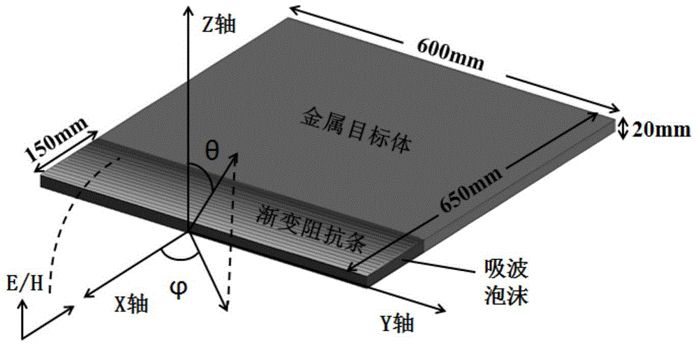
[0029] A rectangular metal plate with a length of 650 mm, a width of 600 mm, and a height of 20 mm is loaded with absorbing foam and gradient impedance strips.

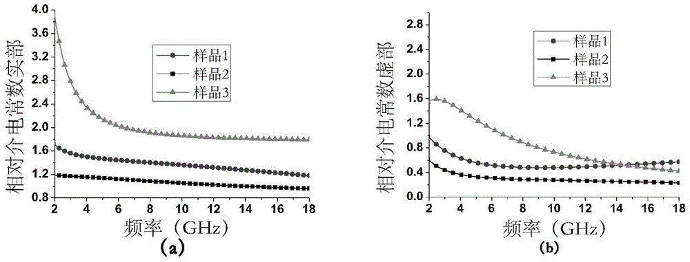
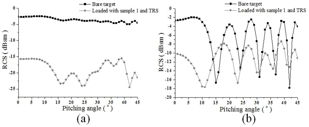
[0030] Set the incident wave frequency to 4GHz. The long axis of the rectangular metal plate is 150mm away from the front edge of the metal plate, and the metal target is cut off along the vertical direction of the long axis. Load absorbing foam as sample 1, and its relative permittivity is 1.1≤ε from 2GHz to 18GHz r '≤1.8, 0.4≤ε r ″≤1.0, to restore the original shape of the metal target. The upper and lower surfaces of the absorbing foam completely cover the gradient impedance strip, and the impedance change of the gradient impedance strip follows the linear change formula R(x)=k*x+b, where k= 6.45, b=-63.5, the gradient impedance bar is divided into 15 sections, and the values ​​of x are 10, 30, 50, 70, 90, 110, 130, 150, 170, 190, 210, 230, 250, 270, 290. Among them, the impedance of the impedance strip at the c...

Embodiment 2

[0033] Load absorbing foam and gradient impedance strips on the elliptical cylindrical metal body with a major semi-axis of 400 mm, a minor semi-axis of 70 mm, and a height of 600 mm.

[0034] Set the frequency of the incident wave to 4 GHz, cut off the metal target along the vertical direction of the long axis at a distance of 150 mm from the front edge of the elliptical cylinder in the direction of the long axis of the ellipse. Load absorbing foam as sample 2, and its relative permittivity is 0.9≤ε from 2GHz to 18GHz r '≤1.2, 0.2≤ε r ″≤0.6, to restore the original shape of the target body. The upper and lower surfaces of the absorbing foam completely cover the gradient impedance strip, and the impedance change of the gradient impedance strip follows the exponential change formula R(x)=e a e b-x Among them, the amplitude factor a=0.05, the index factor b=0.06, the gradient impedance bar is divided into 15 sections, and the values ​​of x are 5, 15, 25, 35, 45, 55, 65, 75, 85...

Embodiment 3

[0037] The metal target body formed by tangentially compounding the two waists of the isosceles triangular prism and the cylinder is loaded with absorbing foam and gradient impedance strips. The bottom surface of the triangular prism is an isosceles triangle with a vertex angle of 33.8°, a side length of 583 mm, and a height of 450 mm. The cylinder has a radius of 180mm and a height of 450mm.

[0038] Set the frequency of the incident wave to 4 GHz, cut off the metal target along the vertical direction of the long axis at a distance of 150 mm from the front edge of the metal target in the direction of the long axis of the metal target. Load absorbing foam as sample 3, and the relative permittivity is 1.8≤ε from 2GHz to 18GHz r '≤4.0, 0.4≤ε r ″≤1.6, to restore the original shape of the target body. The upper and lower surfaces of the absorbing foam completely cover the gradient impedance strip, and the impedance change of the gradient impedance strip follows the exponential c...


PUM


Abstract

The invention discloses an edge scattering restraining method based on combined loading of the microwave absorption foam and gradual change impedance strips, belongs to the technical field of electronic materials, and particularly relates to an electromagnetic wave edge scattering restraining structure and the design and achievement of the electromagnetic wave edge scattering restraining structure. The edge scattering restraining method based on combined loading of the microwave absorption foam and the gradual change impedance strips comprises the steps that shaping is carried out, wherein a metal target body is cut off in the direction perpendicular to the long axis at the position 0.5-4 times of the incidence wave length away from the front edge of the metal target body in the long axis direction; the microwave absorption foam is loaded on the shaped metal target body to enable the metal target body to recover the appearance before shaping; the gradual change impedance strips respectively and completely cover the upper surface layer and the lower surface layer of the microwave absorption foam, and the impedance of each gradual change impedance strip gradually increases from the position making contact with the metal target body to the front edge of the metal target body. The edge scattering restraining method based on combined loading of the microwave absorption foam and the gradual change impedance strips can effectively lower edge scattering of the metal target body, and can control edge scattering under different polarization conditions by reasonably adjusting the relative dielectric constant of the microwave absorption foam. Compared with a method of loading design of extending the impedance strips outside the edge of a target, the edge scattering restraining method based on combined loading of the microwave absorption foam and the gradual change impedance strips has certain mechanical strength, and is easy to apply in actual construction, simple in process, high in maneuverability and easy to popularize.

Description

technical field [0001] The invention belongs to the technical field of electronic materials, and in particular relates to an electromagnetic wave edge scattering suppression structure and its design and realization. Background technique [0002] With the development of detection technology, the survivability of weapons and equipment on the battlefield is seriously threatened, and stealth technology can improve the survivability of weapons and equipment, and is valued by countries all over the world in terms of military affairs. Detection methods mainly include infrared and radar, and radar stealth is still the most important category. The means of realizing radar stealth mainly include shaping design, radar absorbing material, structure loading, passive cancellation or active cancellation. Through shaping optimization, scattering sources that have a strong effect on radar waves, such as mirrors, dihedral angles, and cavities, can be effectively controlled. At this time, th...

Claims


Application Information

Patent Timeline
Patent Type & Authority Applications(China)
IPC IPC(8): H01Q15/00
Inventor 鲁莉娟董晨黄陈陈海燕周佩珩梁迪飞邓龙江谢建良陈良
Owner UNIV OF ELECTRONICS SCI & TECH OF CHINA
Why Eureka
Try Eureka