Automatic compensation device for X-ray detection of weld joint of fuel rod end plug

An automatic compensation and fuel rod technology, which is applied in the field of ray detection, can solve problems such as the inability to ensure consistent distances between ray components, the inability to automatically determine the best transillumination area, and the inability to ensure transillumination welds, etc., to achieve automatic detection and avoid scratches. The effect of scratching the surface and improving the sensitivity of transillumination

Active Publication Date: 2019-05-07
CHINA NUCLEAR BAOTOU GUANGHUA CHEM IND
View PDF5 Cites 3 Cited by
  • Summary
  • Abstract
  • Description
  • Claims
  • Application Information

AI Technical Summary

Problems solved by technology

At present, full compensation or semi-compensation transillumination methods are used in the radiographic inspection of fuel rod end plug welds. The compensation block does not have functions such as automatic opening or automatic shielding according to the number of components. There are scratches on the outer wall of the compensation block; when the number of transillumination is less than the compensation hole, the best transillumination area cannot be automatically determined, and the position of the vacant compensation hole needs to be manually shielded; during the transillumination process, it is impossible to ensure that the ray element enters the compensation hole The distance within the test is consistent, and the transillumination weld seam cannot be guaranteed to be on a straight line, and there is a phenomenon of inconsistency in the transillumination sensitivity when evaluating the test results

Method used


Image

  • Automatic compensation device for X-ray detection of weld joint of fuel rod end plug
  • Automatic compensation device for X-ray detection of weld joint of fuel rod end plug
  • Automatic compensation device for X-ray detection of weld joint of fuel rod end plug

Examples


Embodiment Construction

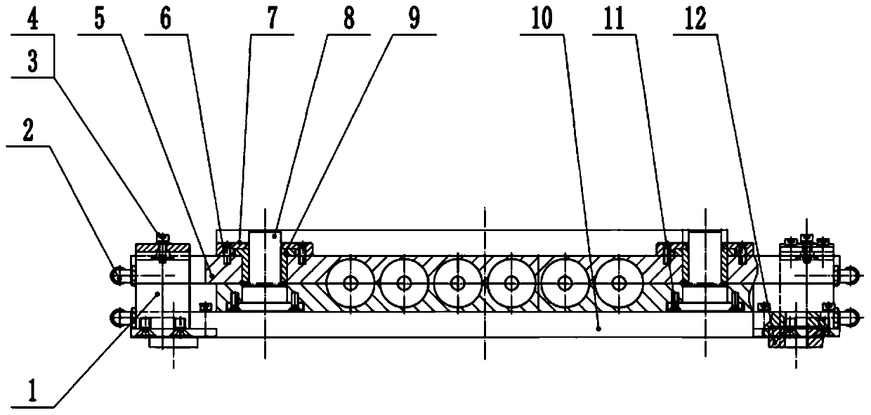
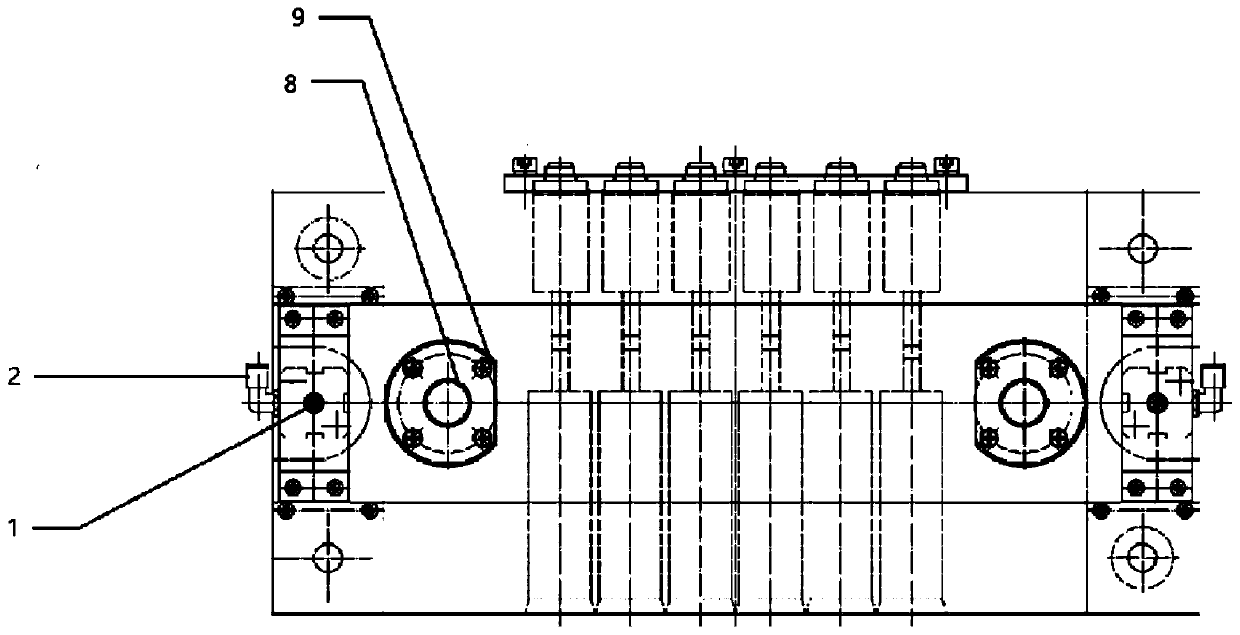
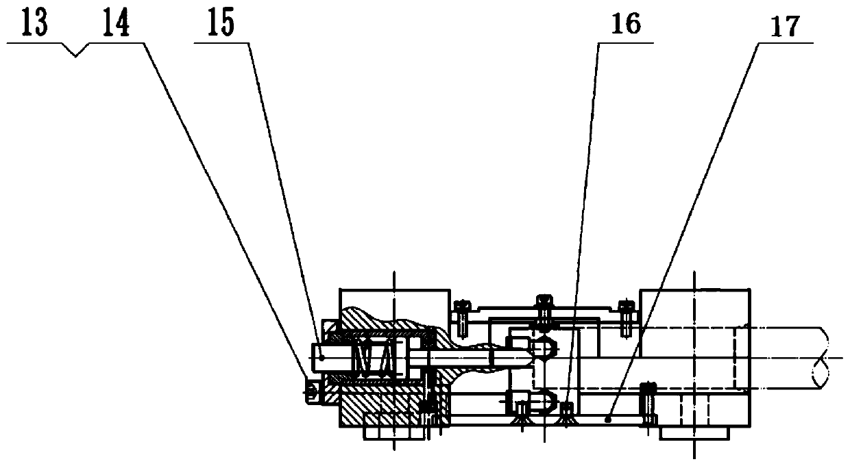
[0046] The present invention will be described in further detail below in conjunction with the accompanying drawings and specific embodiments.

[0047] Such as Figure 1~3 The shown automatic compensation device for X-ray detection of fuel rod end plug welds includes an upper compensation block 5, a lower compensation block 10 and auxiliary components of the compensation block.

[0048] Such as Figure 4 As shown, the upper compensation block 5 is a rectangular plate with a length of 350 mm and a width of 80 mm, and its thickness is greater than the radius of the weld seam of the fuel rod end plug to be detected.

[0049] Two groups of threaded holes are processed on the left and right sides of the upper compensation block 5 . A plurality of compensation grooves are processed at equal intervals on the lower surface of the upper compensation block 5 , and the centerlines of each compensation groove are parallel to each other. The compensation groove is a semicircular groove,...


PUM


Abstract

The invention relates to the technical field of ray detection, and particularly discloses an automatic compensation device for X-ray detection of a weld joint of a fuel rod end plug. Compressed air isintroduced into an ultra-thin air cylinder through an air inlet hole of the ultra-thin air cylinder, and an air outlet of the ultra-thin air cylinder is closed; and the compressed air is blown to thejoint between an upper compensation block and a lower compensation block through an air opening in the ultra-thin air cylinder, so that the upper compensation block moves upwards along a cross-groovecountersunk head screw b and a cross-groove countersunk head screw c to be separated from the lower compensation block. According to the device, automatic compensation in the detection of the weld joint of the fuel rod end plug can be realized, and powerful guarantee is provided for automatic detection of the fuel rod.

Description

technical field [0001] The invention belongs to the technical field of radiation detection, and in particular relates to an automatic compensation device for X-ray detection of fuel rod end plug welds. Background technique [0002] The fuel rods are in a strong neutron field in the reactor, and they are subjected to high temperature, high pressure, and high flow rate coolant, and at the same time bear the chemical action of fissile substances, complex mechanical loads, and steam corrosion. The working conditions are very harsh, and the fuel rods are required to have a high degree of reliability and safety. The fuel rod cladding is the first safety barrier of a nuclear reactor, and the weld between the cladding and the end plug is the weakest link in this barrier, where fission product leakage is prone to occur. Therefore, the welding quality of end plugs directly affects the safe operation of nuclear fuel rods in nuclear reactors, and the welding process and corresponding n...

Claims


Application Information

Patent Timeline
Patent Type & Authority Applications(China)
IPC IPC(8): G21C17/10
CPCY02E30/30
Inventor 张小刚葛腾丛林郑赛春孙有文高崇郭梦雅姜怀花
Owner CHINA NUCLEAR BAOTOU GUANGHUA CHEM IND
Why Eureka
Try Eureka