Rubber extruder

A rubber extruder and discharge port technology, applied in the field of rubber machinery, can solve the problems of low working efficiency, poor quality stability, affecting the production efficiency of rubber extruders and product quality, etc., to achieve good sealing effect and improve quality Effect

Active Publication Date: 2015-12-02
山西丛鑫液压科技集团有限公司
View PDF7 Cites 7 Cited by
  • Summary
  • Abstract
  • Description
  • Claims
  • Application Information

AI Technical Summary

Problems solved by technology

[0003] The traditional rubber extruder often has a large difference in the mixing ratio of rubber and other auxiliary materials when feeding, which affects the quality of the extruded rubber material
In addition, the rotating shaft rotates for a long time, so that after the sealing ring is worn, the rubber material will enter the bearing of the rotating shaft, damage the bearing, and the rotating shaft will fail, resulting in the abnormal operation of the rotating shaft, which will affect the production efficiency of the rubber extruder and the quality of the product. maintenance costs and production costs
[0004] The head of the traditional extruder realizes the production of rubber hose through the annular hole formed by the mold core and the mold sleeve. However, when it is necessary to produce rubber hoses of different thicknesses, it is necessary to start the head, replace the mold core and mold sleeve, and at the same time need to adjust the mold core and mold sleeve. The concentricity of the hose is guaranteed to ensure that the wall thickness of the produced rubber hose is uniform, but it takes at least 30 minutes for each adjustment, and even 1 to 2 hours for unskilled operators. During this period, the rubber material continues to flow out through the nozzle. This causes a lot of waste of raw materials and labor, low work efficiency and poor quality stability

Method used


Image

  • Rubber extruder

Examples


Embodiment Construction

[0014] The present invention will be described in further detail below through specific implementation examples and in conjunction with the accompanying drawings.

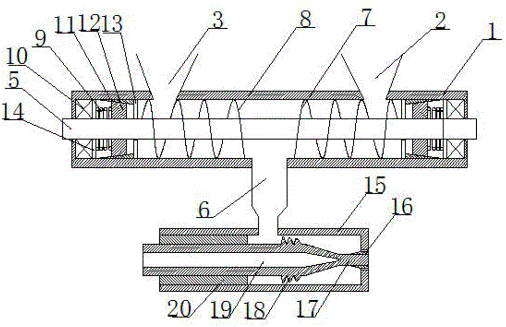
[0015] figure 1 Shown is a rubber extruder provided by the present invention, including a feed cylinder 1, a feed port 2, a glue feed port 3, a rotating shaft 5, a discharge port 6, a first thread 7, a second thread 8, a spring 9. Bearing 10, annular column 11, sealing ring 12, first partition 14, second partition 13, housing 15, mold core sleeve 16, mold core 17, protrusion 18, cavity 19, annular cylinder 20 and Mold cover 21. The rotating shaft 5 is connected with the feeding cylinder 1 through a bearing 10; the two ends of the feeding cylinder 1 are respectively provided with a feed port 2 and a glue inlet 3, and the middle part is provided with a discharge port 6; the two ends of the rotating shaft 5 are The ends are respectively provided with a first section of threads 7 and a second section of threads 8, an...


PUM


Abstract

The invention discloses a rubber extruder. The rubber extruder comprises a feeding cylinder, bearings, a shell and a rotation shaft. Two ends of the rotation shaft are each provided with a section of a thread. The inner walls of the two ends of the feeding cylinder are each provided with a first isolation plate and a second isolation plate. The first isolation plates and the second isolation plates are disposed between the corresponding bearings and the threads. An annular column is arranged between each first isolation plate and the corresponding second isolation plate, and a tapered face is arranged on the inner wall of each annular column. A seal ring is arranged in each annular column and in fit with the annular column through the corresponding tapered face, and a spring is arranged between each seal ring and the corresponding first isolation plate. One end of the shell is fixedly connected with a die sleeve, and a through hole is formed in the center of the die sleeve. An annular cylinder fixedly connected with the inner wall of the shell is arranged in the shell, and a die core is in thread fit connection with the interior of the annular cylinder and penetrates through the shell. A discharging hole is formed between the inner surface of the die sleeve and the outer surface of the die core. A thread is arranged on the outer circular face of the die core, and a die core sleeve in thread fit connection with the die core is arranged on the outer circular face of the die core. By means of the extruder, the extrusion quality of rubber materials and work efficiency can be improved.

Description

technical field [0001] The invention relates to the technical field of rubber machinery, in particular to a rubber extruder. Background technique [0002] Rubber extruder, also known as extruder, is one of the important process equipment in the production of rubber products. In the processing and molding of rubber materials in the rubber industry, rubber extruders and calenders are listed as the two leading production models. They are widely used and can process and manufacture various strips, tubes, rods, plates and other special-shaped rubber materials. And with the development of science and technology, cash rubber extruder can produce plate rubber, steel cord rubber cloth and metal, fiber wire covering rubber and so on. [0003] Traditional rubber extruders often have a large difference in the mixing ratio of rubber and other auxiliary materials when feeding, which affects the quality of the extruded rubber material. In addition, the rotating shaft rotates for a long t...

Claims


Application Information

Patent Timeline
Patent Type & Authority Applications(China)
IPC IPC(8): B29C47/00B29C47/08B29C47/10B29C47/22B29C47/60B29L23/00B29C48/325
CPCB29C48/09B29C48/254B29C48/297B29C48/30B29C48/325B29C48/59B29L2023/22
Inventor 梁庆欢王健强蒋颖李玲玉王川林刘洪波陈长明杜跃武郭勇年黄睿杰
Owner 山西丛鑫液压科技集团有限公司
Why Eureka
Try Eureka