Numerical control type universal polishing unit

A technology of numerical control and polishing mechanism, which is applied to surface polishing machine tools, grinding/polishing equipment, and parts of grinding machine tools.

Inactive Publication Date: 2015-05-13
南通金庆美术图案设计有限公司
View PDF8 Cites 9 Cited by
  • Summary
  • Abstract
  • Description
  • Claims
  • Application Information

AI Technical Summary

Problems solved by technology

[0003] Aiming at the defects existing in the prior art, the present invention provides a numerically controlled universal polishing unit, which mainly

Method used


Image

  • Numerical control type universal polishing unit
  • Numerical control type universal polishing unit
  • Numerical control type universal polishing unit

Examples


Embodiment Construction

[0031] The present invention will be further described below in conjunction with the accompanying drawings and embodiments.

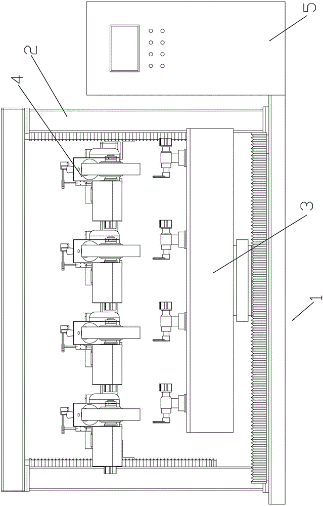
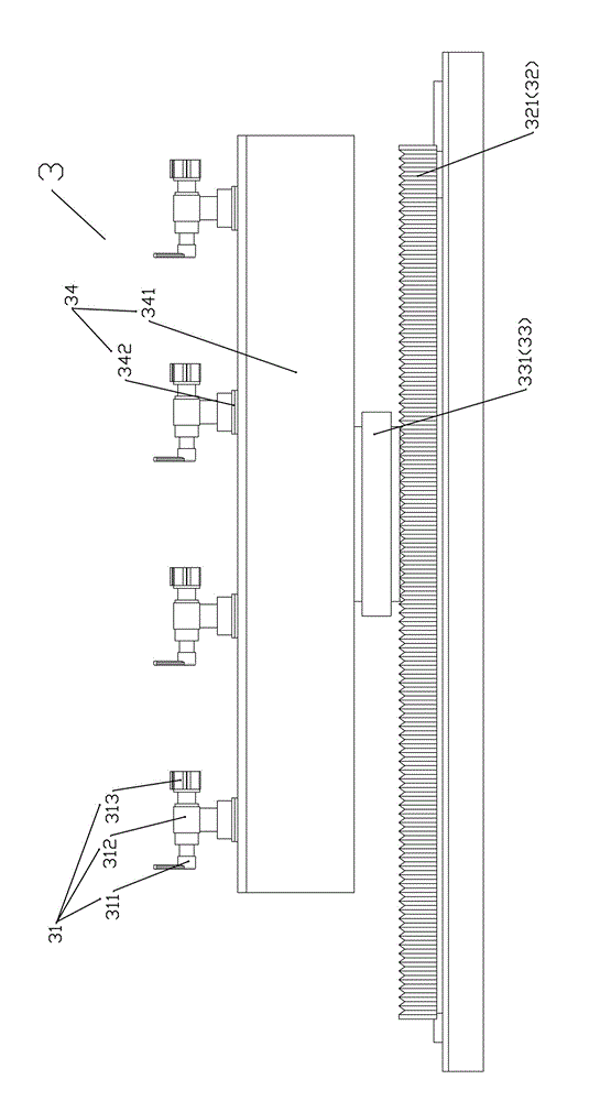
[0032] refer to Figure 1-Figure 3 The CNC type universal polishing unit shown in the figure has a machine base 1, a gantry 2 is fixed on the machine base 1, a product clamping mechanism 3 is installed on the machine base 1, a polishing mechanism 4 is installed on the gantry 2, and a product clamping mechanism is installed 3 cooperate with each other to polish the product, the product clamping mechanism 3 and the polishing mechanism 4 are controlled by the electric control device 5; wherein:

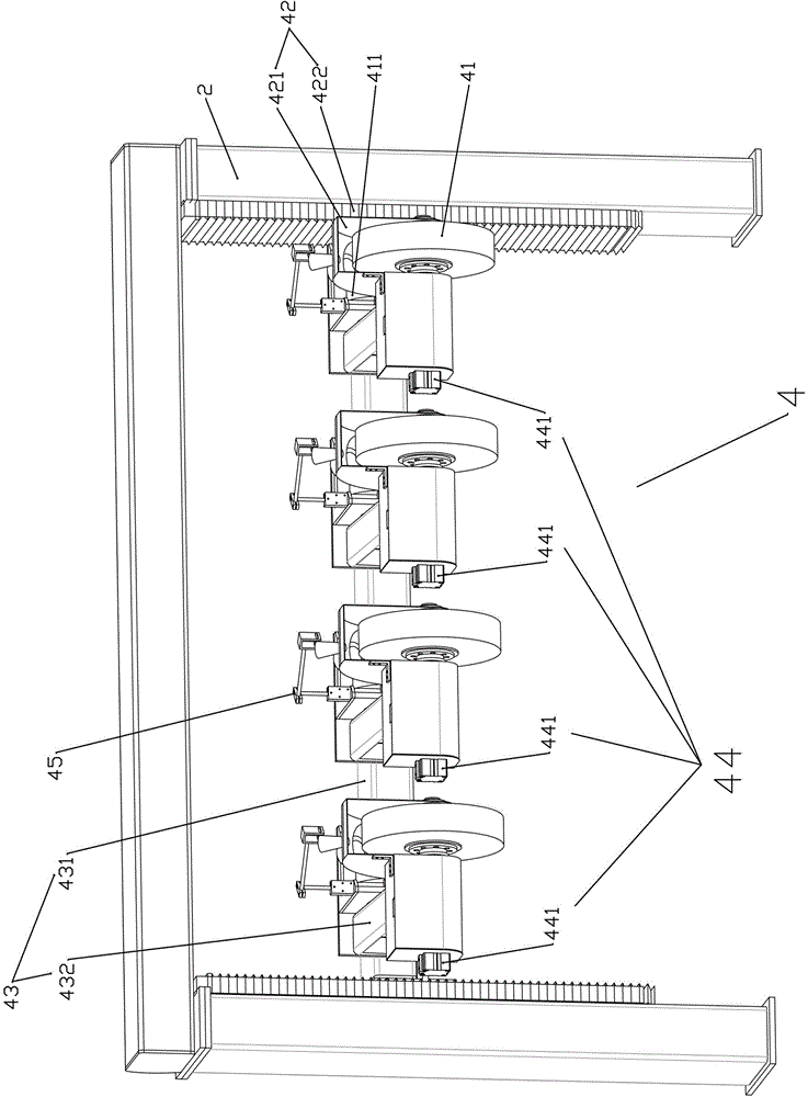
[0033] Polishing mechanism 4 comprises a group of polishing wheels 41 (four in the embodiment), moving assembly 42 up and down, 360 degree rotating assembly 43, polishing wheel swinging assembly 44 and spray gun assembly 45; and the polishing wheel swing assembly 44 cooperate with each other to drive the polishing wheel 41 to move up and down, rotate 360 ​​degree...


PUM


Abstract

The invention relates to a numerical control type universal polishing unit. A portal frame is fixed to a machine base, the machine base is provided with a product clamping mechanism, a polishing mechanism is installed on the portal frame, and the product clamping mechanism and the polishing mechanism are controlled to act by an electric control device. The polishing mechanism comprises polishing wheels, an up-and-down moving assembly, a 360-degree rotating assembly, a polishing wheel swing assembly and a spray gun assembly. The product clamping mechanism comprises a product installation jig, a jig front-and-back moving assembly, a jig left-and-right moving assembly and a jig rotating assembly. Quality is stable, and the production efficiency is high.

Description

technical field [0001] The invention relates to a polishing unit, in particular to a numerically controlled universal polishing unit for cleaning sanitary ware, hardware industry faucets, locks, handles and other special-shaped workpieces. Background technique [0002] The existing sanitary ware, hardware industry faucets, locks, handles and other special-shaped workpieces are generally cleaned by manual polishing, which makes the working environment of the workshop harsh, and the polished dust is metal, which is prone to occupational diseases. Manual polishing, many external factors, unstable product quality, more waste products, serious waste of resources. The cost of training workers is very high, and the training period for skilled polishing workers is 1-2 years, which requires high physical fitness of workers. Labor intensity is very big, and production efficiency is low. Contents of the invention [0003] Aiming at the defects existing in the prior art, the present...

Claims


Application Information

Patent Timeline
IPC IPC(8): B24B29/00B24B41/00B24B41/06
CPCB24B27/0076B24B29/02B24B41/00B24B41/06
Inventor 王炳辉张绍武
Owner 南通金庆美术图案设计有限公司
Why Eureka
Try Eureka