
Motor vehicle drive train comprising hydrodynamic retarder

A drive train, motor vehicle technology, applied in hydraulic brakes, hydraulic resistance brakes, brakes, etc., can solve problems such as large structural space

Inactive Publication Date: 2014-08-13
VOITH PATENT GMBH
View PDF5 Cites 3 Cited by
  • Summary
  • Abstract
  • Description
  • Claims
  • Application Information

AI Technical Summary

Problems solved by technology

[0003] The latter solution in particular, although it does have a high potential for effectively avoiding circular flows in the working space, usually requires an enormous amount of construction space

Method used


Image

  • Motor vehicle drive train comprising hydrodynamic retarder
  • Motor vehicle drive train comprising hydrodynamic retarder
  • Motor vehicle drive train comprising hydrodynamic retarder

Examples


Embodiment Construction

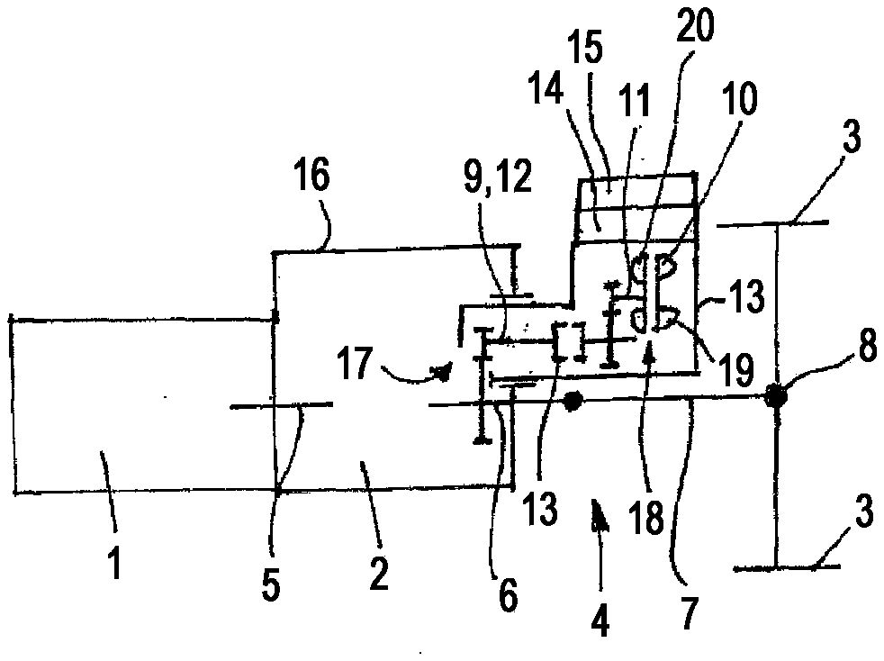
[0020] figure 1 2 schematically shows a motor vehicle drive train according to the invention with a drive motor 1 , a transmission 2 , in particular a cascade transmission or a continuously variable transmission, and drive wheels 3 driven by the drive motor 1 via the transmission 2 . Correspondingly, the main road 4 of the drive train of the motor vehicle extends from the drive motor 1 via the transmission input shaft 5 , the transmission output shaft 6 and the usual cardan shaft 5 on the differential drive 8 to the driven wheels 3 .

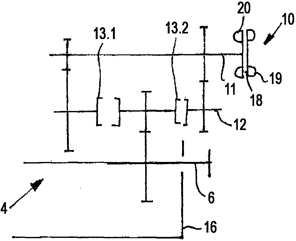
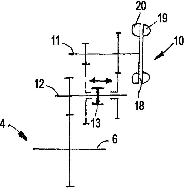
[0021] The transmission 2 has an auxiliary drive train on the secondary side with an auxiliary output shaft 9 which is drivingly connected to the transmission drive shaft 6 via a spur gear pair. With regard to the connection of the hydraulic gear unit 10 or its rotor shaft 11 , the auxiliary output shaft 9 is at the same time the intermediate shaft 12 of the connection according to the invention.

[0022] The countershaft 12 has a disconnect cl...


PUM


Abstract

The invention relates to a motor vehicle drive train including a driving engine and driven wheels. The driven wheels are driven by the driving engine via a main branch. The drive train further includes a hydrodynamic retarder comprising a revolving rotor and a stator or a revolving rotor and a counter-rotating twin rotor which jointly form a working chamber that is or can be filled with a working medium. The drive train also includes a disconnect clutch which allows the rotor of the hydrodynamic retarder to be disengaged from a driving power flow in the drive train. The motor vehicle drive train is characterized in that the hydrodynamic retarder is connected to the main branch via an at least two-stage transmission comprising at least one intermediate shaft and a rotor shaft which drives or supports the rotor, the intermediate shaft forming at least one first transmission stage along with the main branch while forming at least one second transmission stage along with the rotor shaft, and furthermore, the disconnect clutch is arranged on the intermediate shaft.

Description

technical field [0001] The invention relates to a drive train of a motor vehicle with a hydraulic retarder, the details of which are in accordance with the preamble of claim 1 . Background technique [0002] In motor vehicle drive trains, in particular of trucks, hydraulic retarders have already been proposed as wear-free permanent braking devices. However, the acceptance of hydraulic brakes by commercial vehicle manufacturers is based on the fact that such hydraulic brakes have extremely low idling losses during non-braking operation. In order to reduce the idling losses during non-braking operation, various measures are usually taken. One of these measures is the provision of so-called ventilation baffles which are inserted into the gap between the rotor and the stator during non-braking operation, thereby preventing the circulation of air or air-residual working medium-mixture. Further measures provide that during the transition from braking operation to non-braking ope...

Claims


Application Information

Patent Timeline
Patent Type & Authority Applications(China)
IPC IPC(8): B60T1/087B60T10/02F16D57/04
CPCF16D57/04B60T10/02F16H47/06
Inventor 阿希姆·梅内蒂尔曼·胡思迪特尔·劳克曼维尔纳·科克维尔纳·克莱门特马丁·贝克
Owner VOITH PATENT GMBH
Learn More