Combustion turbine in which combustion is intermittent

A gas turbine and turbine technology, applied in combustion chambers, combustion methods, combustion equipment, etc., can solve problems such as unbalanced flow, power output, loss, etc., to avoid output loss, compact and linear structure, and improve acoustics. coupling effect

Active Publication Date: 2011-08-24
赫尔穆斯·加勃尔 +2
View PDF8 Cites 0 Cited by
  • Summary
  • Abstract
  • Description
  • Claims
  • Application Information

AI Technical Summary

Problems solved by technology

This diversion results in an unbalanced flow to the turbine and loss of power output

Method used


Image

  • Combustion turbine in which combustion is intermittent
  • Combustion turbine in which combustion is intermittent
  • Combustion turbine in which combustion is intermittent

Examples


Embodiment Construction

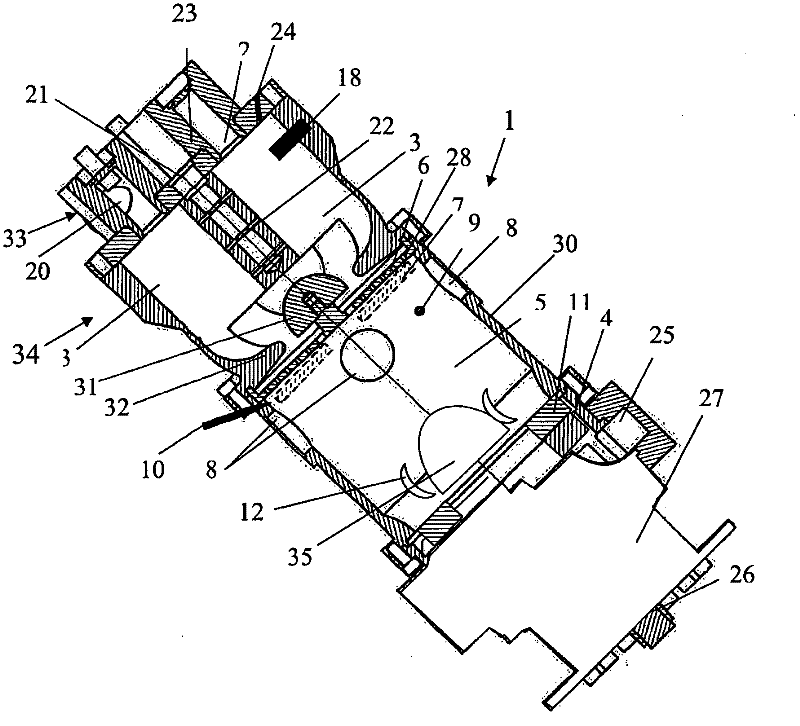
[0036] figure 1 Shown is a longitudinal section through a possible embodiment of the invention. The depicted gas turbine 1 essentially consists of a primary valve head 33 , a combustion chamber region 34 , a subsequent flow chamber 5 , a turbine 4 and a drive shaft 26 with a bearing housing 27 .

[0037] The primary valve head 33 is firmly connected to the combustion chamber region 34 and it delineates the upper side of the combustion chamber 3 . The inlet valve 2 arranged in the valve holder 23 is housed inside the primary valve head 33 .

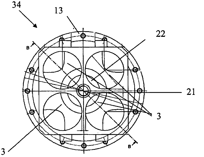
[0038] In the present example, the combustion chamber area 34 comprises four cylindrical combustion chambers 3 into which air is fed via air inlet openings 20 , inlet valves 2 , and fuel via a fuel supply system 24 , respectively. The fuel supply system 24 can be designed as one or several injection nozzles (a single nozzle or a bank of nozzles, such as piezoelectric injectors).

[0039]It is also conceivable to add fuel to the air outs...


PUM


Abstract

The invention relates to a combustion turbine (1) in which combustion is intermittent and which comprises at least one combustion chamber (3) that has intake valves (2) and an ignition device (18). The at least one combustion chamber (3) has no blocking devices at the exhaust end and is therefore constantly open at the exhaust end. A turbine (4), to which a working gas obtained in the combustion chamber (3) can be fed, is arranged downstream of the at least one combustion chamber (3). A flow chamber (5) is arranged axially behind the at least one combustion chamber (3), between the at least one combustion chamber (3) and the turbine (4). The flow chamber (5) is delimited from the at least one combustion chamber (3) by a flow plate (6) or another turbine (7). The invention also relates to a method for operating a combustion turbine (1) as well as a drive system for a machine comprising the claimed combustion turbine (1) as the essential piece.

Description

technical field [0001] The subject of the invention is a gas turbine for discontinuous combustion with at least one combustion chamber having an inlet valve or an inlet valve and an ignition device. The at least one combustion chamber has no shut-off device on the exhaust side, so the exhaust side is always open. Downstream of the at least one combustion chamber there is provided a turbine which can be struck by the process gas (Arbeitsgas) obtained in the combustion chamber. A flow-through chamber is positioned between the combustor and the turbine, axially behind the combustor. [0002] Further, the subject of the invention is a method for operating a gas turbine. [0003] The invention also relates to a drive system for a machine having as its core a gas turbine according to the invention. Background technique [0004] On the one hand, conventional, state-of-the-art turboengines constantly lose energy due to the air compression process (compressor work) required before...

Claims


Application Information

Patent Timeline
Patent Type & Authority Applications(China)
IPC IPC(8): F02C5/12F23R7/00F02K7/06
CPCF02C5/12Y02T50/671F02K7/06F02C5/02F23R7/00Y02T50/60
Inventor 赫尔穆斯·加勃尔埃德蒙德·洛伦茨弗朗茨·尼德尔
Owner 赫尔穆斯·加勃尔
Why Eureka
Try Eureka