Master cylinder with flow restriction system

A technology of brake fluid and main pressure, used in brakes, brake transmissions, hydraulic brake transmissions, etc.

Active Publication Date: 2017-07-11
ROBERT BOSCH GMBH
View PDF1 Cites 0 Cited by
  • Summary
  • Abstract
  • Description
  • Claims
  • Application Information

AI Technical Summary

Problems solved by technology

When the pushrod is released quickly, it may cause the brake fluid in the master cylinder pressure chamber to pass through at atmospheric pressure due to the spring action pushing the piston faster than the brake fluid reaches the master cylinder

Method used


Image

  • Master cylinder with flow restriction system
  • Master cylinder with flow restriction system
  • Master cylinder with flow restriction system

Examples


Embodiment Construction

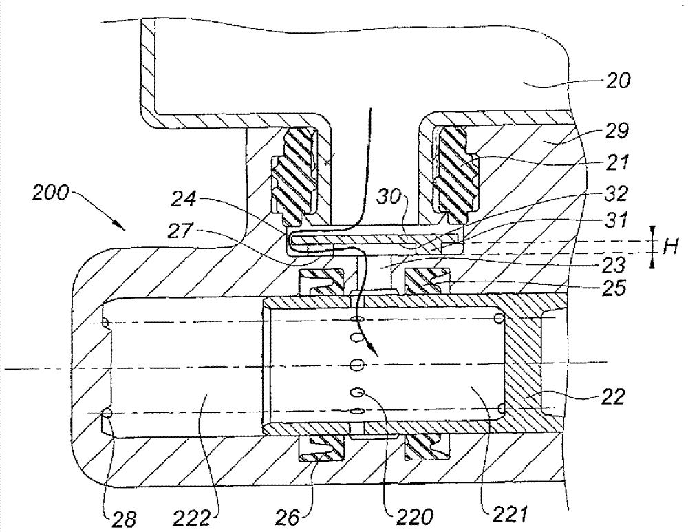
[0060] figure 1 The master brake cylinder 100 is shown with a bore 11 that receives the primary piston 2 , the secondary piston 3 and the primary spring 7 and secondary spring 8 . The function of the pistons 2, 3 is to bring the main pressure chamber 9 and the auxiliary pressure chamber 10 under pressure. The brake fluid supply inlets 12, 13 are used for connection with a brake fluid container (not shown). Two sides of the inlet hole 12 are provided with sealing covers 33 and 4 , and two sides of the inlet hole 13 are provided with sealing covers 5 and 6 . When the master cylinder is at rest, the master piston 2 is in figure 1 in the position shown. The walls of the pistons 2 , 3 provided with passages 14 , 15 communicate the perforations 12 , 13 with the interior of each piston 2 , 3 and with the primary 9 and secondary 8 pressure chambers. At rest, the sealing caps 4, 6 allow communication between the inlets 12, 13 and the main and auxiliary pressure chambers 9, 10, whic...


PUM


Abstract

The invention relates to a master cylinder (200) equipped with a brake fluid container (20) connected through its neck (201), the neck forming a chamber (24) with the main body (29) of the master cylinder through a perforated (23) is connected with the (main or auxiliary) pressure chamber of the master cylinder through the hole (220) of the piston (22). The chamber receives a cover (30) which restricts the flow of brake fluid drawn into the chamber (222) around the piston (22) in its rest position.

Description

technical field [0001] The invention relates to a master cylinder equipped with a brake fluid container connected to the master cylinder by its goulot engaging in a perforation in the upper part of the master cylinder to pass through the perforation through the wall of the master cylinder when the piston is at rest And through the hole of the piston (main and / or auxiliary piston) to communicate with the pressure chamber. Background technique [0002] Known master cylinders include a primary piston and a secondary piston, usually made of aluminum, and both are mounted in series in an axial bore of the body of a brake master cylinder, usually made of machined aluminum. Such a master cylinder is described in document FR2827244. A push rod in the cavity of the primary piston allows to actuate the movement of the primary piston which puts the primary pressure chamber under pressure and the secondary piston under pressure. The primary and secondary springs push the piston in opp...

Claims


Application Information

Patent Timeline
Patent Type & Authority Patents(China)
IPC IPC(8): B60T11/22B60T11/232B60T11/20
CPCB60T11/20B60T11/22B60T11/232B60T11/224
Inventor L.吕利耶M.罗德里古茨
Owner ROBERT BOSCH GMBH
Why Eureka
Try Eureka