Synchronous door moving mechanism of drive-by-wire automatic vehicle door

A driving mechanism and automatic technology, applied in the direction of power control mechanism, wing fan control mechanism, door/window fittings, etc. Comfort, cost reduction, effect of simple structure

Inactive Publication Date: 2021-08-10
开沃新能源汽车集团股份有限公司
View PDF6 Cites 0 Cited by
  • Summary
  • Abstract
  • Description
  • Claims
  • Application Information

AI Technical Summary

Problems solved by technology

[0003] In the current wire-controlled automatic door products, there are often phenomena such as asynchronous opening and closing of the door, the door is not closed tightly, loud shaking noise or water leakage, etc.
The reason for these phenomena is mainly because the structural motion control is not synchronized, and the door panel cannot be restricted or adjusted, resulting in poor reliability.

Method used


Image

  • Synchronous door moving mechanism of drive-by-wire automatic vehicle door
  • Synchronous door moving mechanism of drive-by-wire automatic vehicle door
  • Synchronous door moving mechanism of drive-by-wire automatic vehicle door

Examples


Embodiment Construction

[0018] The present invention will be further described below in conjunction with the accompanying drawings.

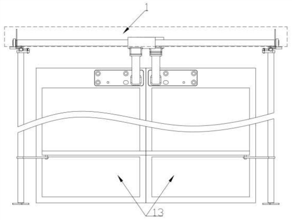
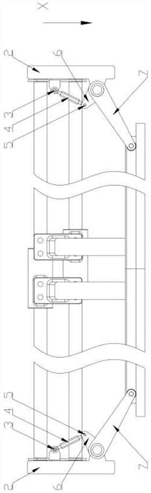
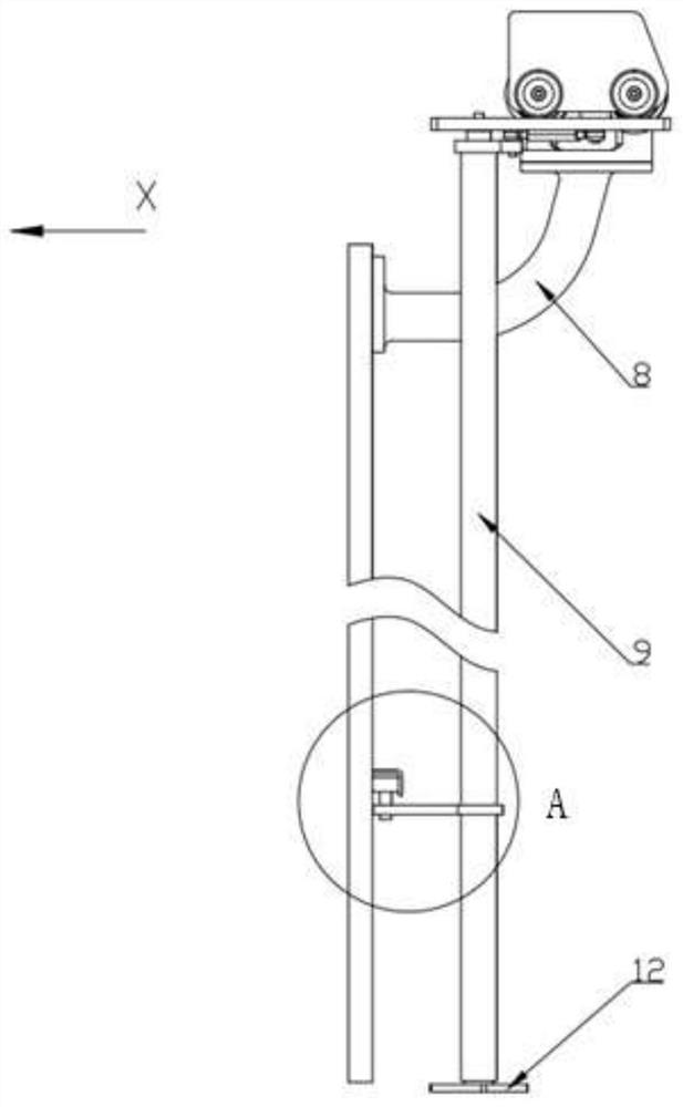
[0019] The synchronous sliding door of the wire-controlled automatic car door of the present invention comprises vehicle frame, driving mechanism 1, bracket 2, first pin shaft 3, push rod 4, second pin shaft 5, upper swing arm 6, lower swing arm 7, carrying Door frame 8 , synchronous rod 9 , slide rail 10 , slide bar 11 , base 12 and door panel 13 . Wherein the base 12 and the bracket 2 are installed on the vehicle frame, and the bracket 2 is located above the base 12 . The synchronization rod 9 is supported between the base 12 and the bracket 2 . The driving mechanism 1 is installed on the bracket 2 and can move along the X direction on the bracket 2. The first pin shaft 3 is connected and fixed between the driving mechanism 1 and the push rod 4. One end of the push rod 4 is connected to the first pin shaft 3 The other end is connected with the second pin shaft 5, t...


PUM


Abstract

The invention discloses a synchronous door moving door of a drive-by-wire automatic vehicle door. The synchronous door moving door of the drive-by-wire automatic vehicle door is characterized in that a base and a support are mounted on a whole vehicle frame, a synchronous rod is supported between the base and the support, a driving mechanism is mounted on the support and can move on the support, a first pin shaft is fixedly connected between the driving mechanism and a push rod, one tail end of the push rod is connected with the first pin shaft, and the other tail end of the push rod is connected with a second pin shaft; the second pin shaft is fixedly connected between the push rod and an upper swing arm, one tail end of the swing arm is fixed on the synchronous rod, the other tail end of the swing arm is fixedly connected with the second pin shaft, the upper swing arm axially rotates along with the synchronous rod, one tail end of the lower swing arm is fixed on the synchronous rod, and the other tail end of the lower swing arm is fixedly connected with a sliding rod; the lower swing arm axially rotates along with the synchronous rod, one tail end of a door carrying frame is fixed to the driving mechanism, the other tail end of the door carrying frame is fixed to a door panel, a sliding rail is fixed to the door panel, the sliding rod is mounted on the lower swing arm, and the outer ring of the sliding rod makes contact with the sliding rail and moves in the sliding rail. According to the synchronous door moving door of the drive-by-wire automatic vehicle door, the synchronous displacement function of the upper and lower ends of the door panel is achieved.

Description

Technical field: [0001] The invention relates to the technology of automatic doors for automobiles, in particular to a synchronous sliding door mechanism for wire-controlled automatic doors, which belongs to the technical field of unmanned automobiles. Background technique: [0002] As far as my country's automobile manufacturing industry is concerned, the application and development of unmanned vehicles has become a major trend, and the development and application of unmanned vehicles not only improves the level of my country's automobile manufacturing technology, but also eases traffic to a certain extent. Pressure, to facilitate people's travel. As a key component of driverless cars, the technical application of wire-controlled automatic doors is particularly important. At present, most of the wire-controlled automatic doors in China can accept the instructions of the whole vehicle, and drive the transmission mechanism through the motor or cylinder to drive the door panel ...

Claims


Application Information

Patent Timeline
Patent Type & Authority Applications(China)
IPC IPC(8): E05F15/56E05F15/655E05F15/649E05F17/00
CPCE05F15/56E05F15/655E05F15/649E05F17/004E05F2017/005E05Y2900/531
Inventor 马跃龙黄斌谢宁仲文诗刘立军
Owner 开沃新能源汽车集团股份有限公司
Why Eureka
Try Eureka