Supercharge Your Innovation With Domain-Expert AI Agents!

Protected powder metal stator core and solenoid actuator using same

A stator core and solenoid technology, applied in the direction of magnetic core/yoke, engine components, machine/engine, etc., can solve problems such as corrosion, performance reduction, protective coating occupation, etc.

Active Publication Date: 2014-08-13
CATERPILLAR INC
View PDF6 Cites 8 Cited by
  • Summary
  • Abstract
  • Description
  • Claims
  • Application Information

AI Technical Summary

Problems solved by technology

Thus, the '008 publication still teaches a mechanism wherein the soft powder metal core is in direct contact with the moving fuel throughout the life of the fuel injector due to released powder particles at strategic locations in the fuel injector, This may cause corrosion, reduced performance and potential failure
Furthermore, while this document teaches a solution for protecting the mostly soft powder metal stator core from cracking, it also teaches the use of non-ferromagnetic plating, which results in the use of valuable space that could be used to carry magnetic flux. The protective coating occupied by the supporting magnetic field

Method used


Image

  • Protected powder metal stator core and solenoid actuator using same
  • Protected powder metal stator core and solenoid actuator using same
  • Protected powder metal stator core and solenoid actuator using same

Examples


Embodiment Construction

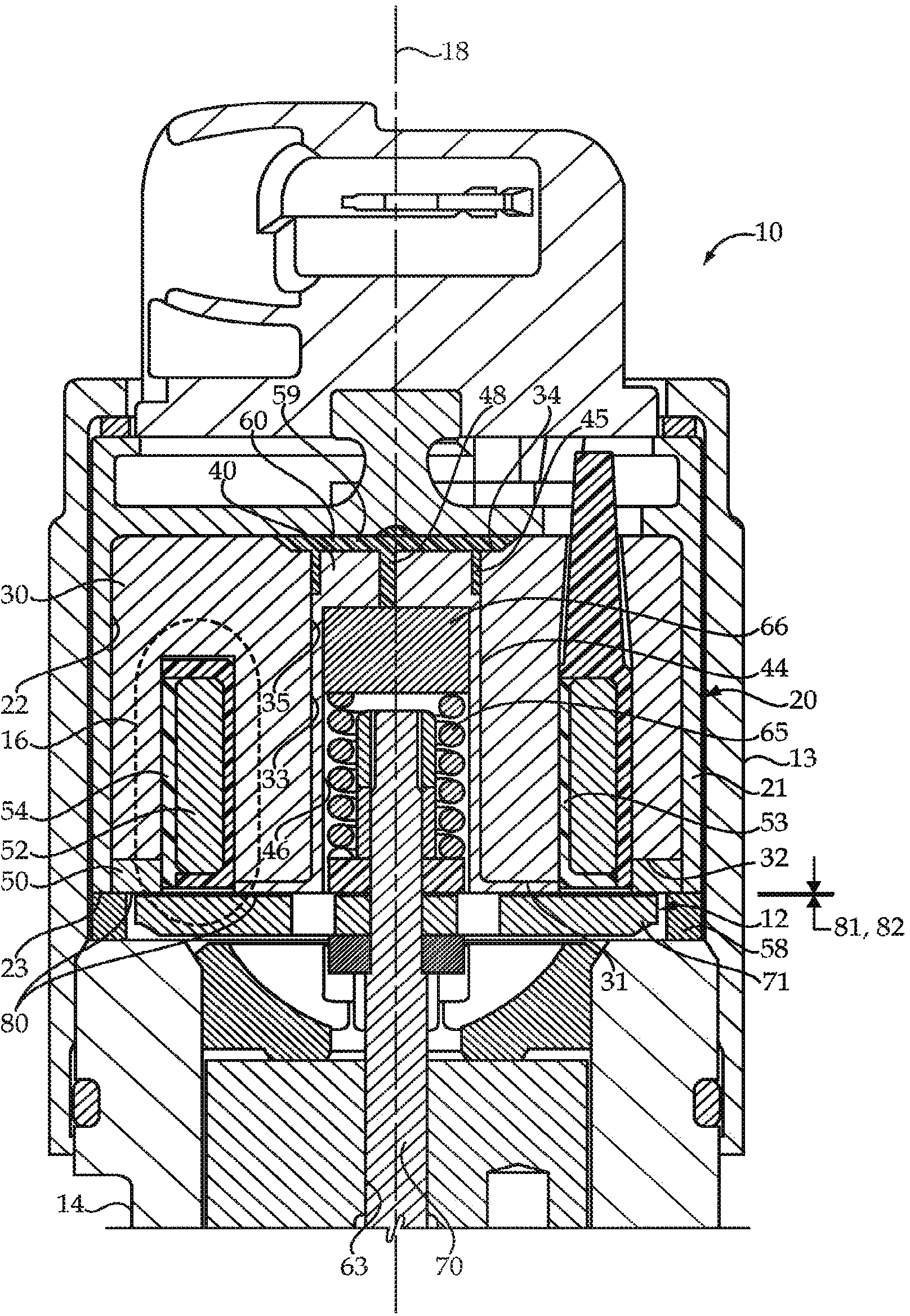
[0015] refer to figure 1 , a solenoid actuator 10 is shown as may be present in the upper half of a common rail fuel injector for an electronically controlled compression ignition engine. The solenoid actuator 10 includes a stator assembly 20 and an armature assembly 12 within an actuator housing 13 and body 14 . Armature assembly 12 is normally biased downwardly and away from stator assembly 20 by biasing spring 65 . When the coil 52 of the stator assembly 20 is energized, magnetic flux lines are generated around the coil 52 to attract the armature assembly 12 toward the stator assembly 20 . The armature assembly 12 moves from the initial air gap 81 towards the final air gap 82, and the travel distance corresponding to the distance between these two air gaps can be so small that at figure 1 almost invisible in view. Regardless, the armature assembly 12 does not contact the stator assembly throughout its travel from the initial air gap 81 towards the final air gap 82 .

[...


PUM


Abstract

A solenoid actuator (10) includes a stator assembly (20) with a stator core (30) of formed powder metal received in a stator housing (21). A ferromagnetic protective sleeve (40) is in contact with and covers a majority of an inner end face (31) and a cylindrical wall (33) of the stator core (30), while a flux ring (50) is in contact with and covers an outer end face (32) of the stator core (30). An armature assembly (12) includes an armature (70) attached to a stem (71) that is movable in an air gap (81) relative to the ferromagnetic protective sleeve (40). A spring (65) is operably positioned in the ferromagnetic protective sleeve (40) but electrically isolated from the stator housing (21). The stator core (30) is encapsulated to protect against erosion and fragmentation. A magnetic flux line (16) around a solenoid coil (52) passes through the stator core (30), the ferromagnetic protective sleeve (40), the armature (70), the flux ring (50) and back to the stator core (30).

Description

technical field [0001] The present invention relates generally to solenoid actuators, such as for fuel injector applications, and more particularly, to a multifunctional ferromagnetic boot for solenoid stator assemblies using powdered metal stator cores. Background technique [0002] Solenoid actuators are widely used in fuel injectors to move control valves in order to precisely control fluid connections in fuel injectors to control injection timing and quantity. As performance requirements continue to increase, industry continues to seek new materials and assembly solutions to improve existing solenoid actuators. One approach that has shown promise for improving performance involves the use of soft powdered metals in the formation of the solenoid actuator's stator core. It is known for this material that it exhibits better permeability properties than ferromagnetic alloy materials. On the downside, the individual particles of the powder in the stator core are less cohesi...

Claims


Application Information

Patent Timeline
Patent Type & Authority Applications(China)
IPC IPC(8): F02M61/16F02M51/06F16K31/02H02K33/02
CPCH01F7/081H01F3/08Y10T29/49009
Inventor J·K·文卡塔拉加万S·谢赫D·R·易卜拉欣M·C·朗N·N·巴尼
Owner CATERPILLAR INC
Features
  • R&D
  • Intellectual Property
  • Life Sciences
  • Materials
  • Tech Scout
  • Unparalleled Data Quality
  • Higher Quality Content
  • 60% Fewer Hallucinations
Learn More