Hall-effect thruster
A Hall effect and thruster technology, applied in aircraft, thrust reverser, machine/engine, etc.
- Summary
- Abstract
- Description
- Claims
- Application Information
AI Technical Summary
Problems solved by technology
Method used
Image
Examples
Embodiment Construction
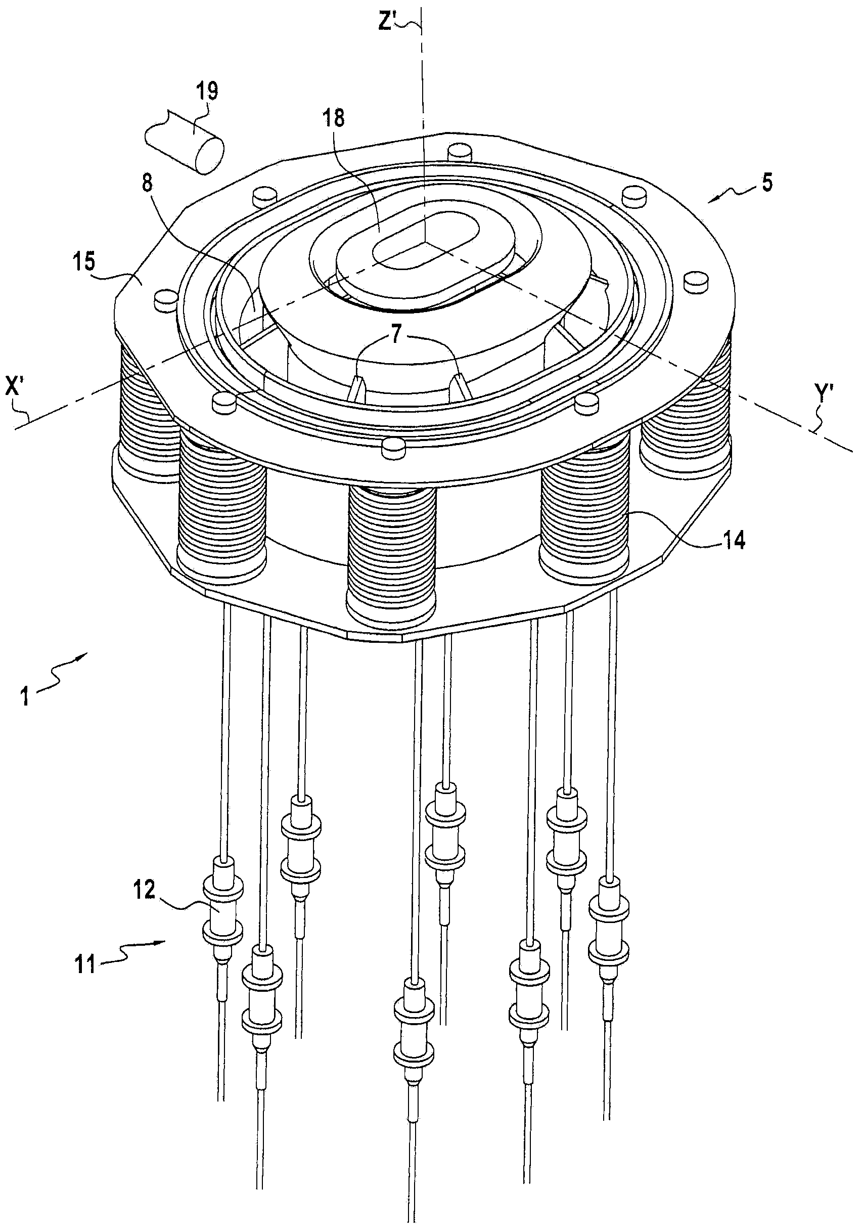
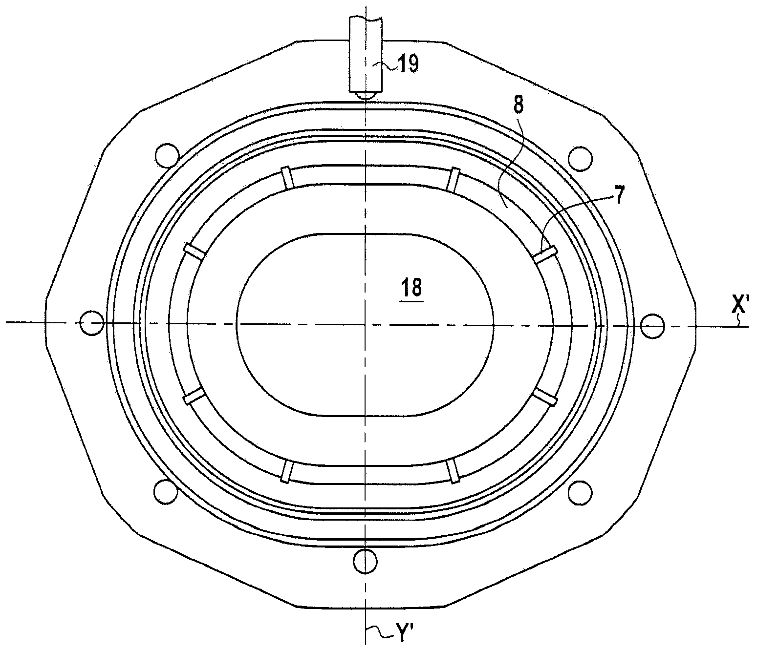
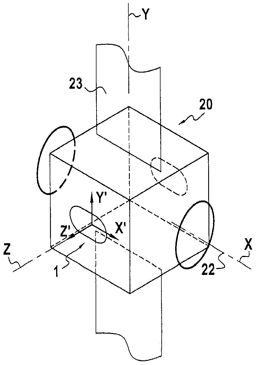
[0027] figure 1 , Figure 1A with Figure 1B Different views of the same Hall effect thruster 1 in one embodiment are shown. The propeller 1 has an annular channel 2 delimited by two concentric walls 3, 4 around a central axis Z', these concentric walls being made of ceramic material. The annular channel 2 has an open end 5 and a closed end 6 . Next to the closed end 6 , radial walls 7 subdivide the upstream section 2 a of the annular channel 2 into separate compartments 8 . At the closed end 6 the annular channel 2 also has an anode 9 which can be separated from a plurality of compartments 8 and a nozzle 10 for injecting propellant gas into each compartment 8 . The nozzles 10 are connected to a source of propellant gas through an injection circuit 11 comprising individual flow rate regulator means 12 for each nozzle 10 . For example, each device 12 may be a pencil valve or a thermo-capillary; a thermo-capillary is a capillary with heating means to actively control its ow...
PUM
 Abstract
Description
Claims
Application Information
 - R&D
- Intellectual Property
- Life Sciences
- Materials
- Tech Scout
- Unparalleled Data Quality
- Higher Quality Content
- 60% Fewer Hallucinations
Browse by: Latest US Patents, China's latest patents, Technical Efficacy Thesaurus, Application Domain, Technology Topic, Popular Technical Reports.
© 2025 PatSnap. All rights reserved.Legal|Privacy policy|Modern Slavery Act Transparency Statement|Sitemap|About US| Contact US: help@patsnap.com


