
Method for controlling the direction of an aircraft, and aircraft designed to implement said method

A technology for airplanes, wings, applied in the field of aviation, which can solve the problems of increased complexity, lack of reliability, fragility, etc.

Pending Publication Date: 2020-09-18
阿内莫斯科技有限公司
View PDF5 Cites 0 Cited by
  • Summary
  • Abstract
  • Description
  • Claims
  • Application Information

AI Technical Summary

Problems solved by technology

[0011] The disadvantage of the aileron / tail control system is that it adds extra weight, and more importantly, the solution increases the complexity in industrialization and is relatively fragile and lacks reliability
[0012] In the absence of a large and sufficiently effective tail, another disadvantage of such a system is that, in addition to the desired roll motion, it also produces a yaw motion that is the opposite of the roll motion, or "navigation" for short

Method used


Image

  • Method for controlling the direction of an aircraft, and aircraft designed to implement said method
  • Method for controlling the direction of an aircraft, and aircraft designed to implement said method
  • Method for controlling the direction of an aircraft, and aircraft designed to implement said method

Examples


Embodiment Construction

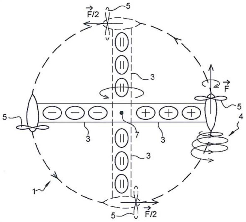
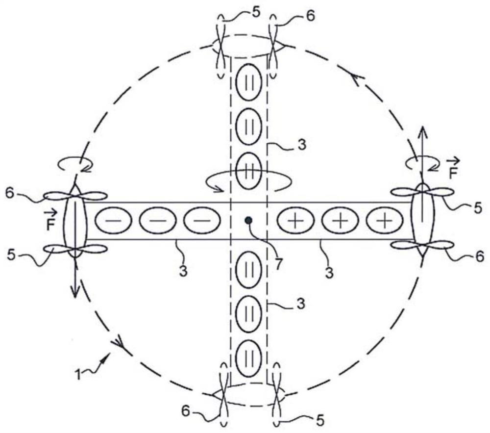
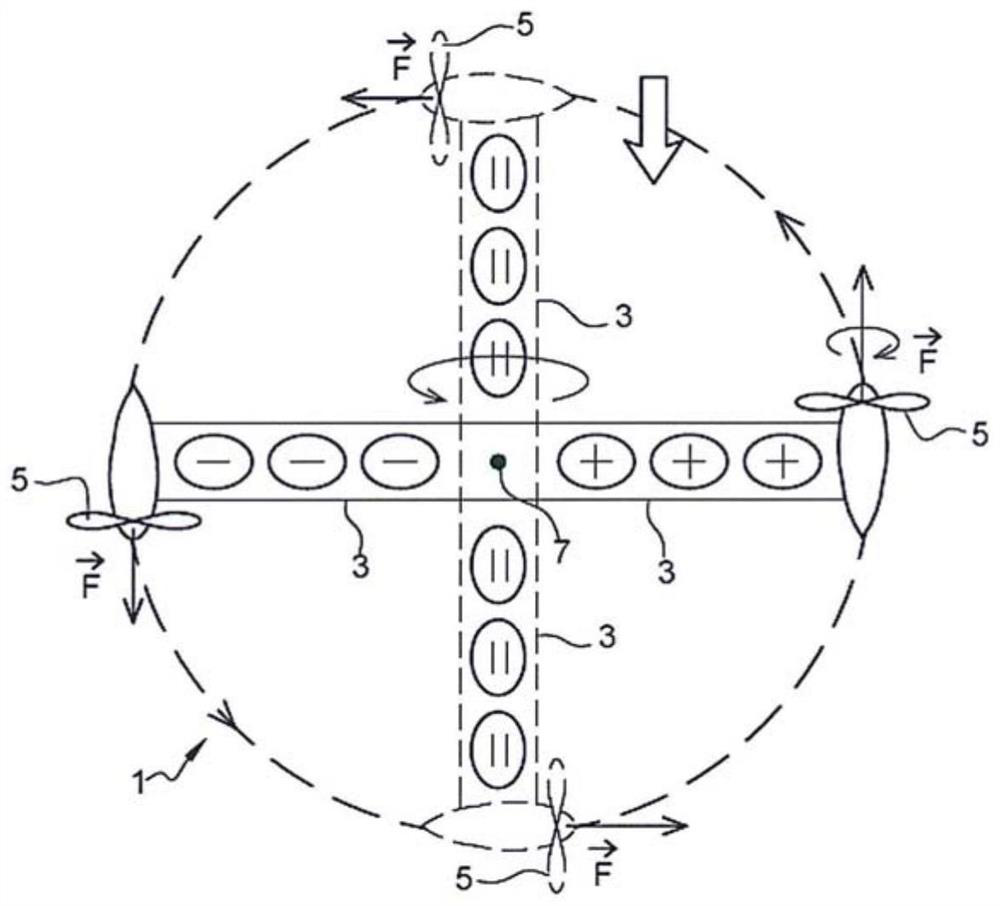
[0046] The invention relates to a method for controlling the direction of an aircraft (1). Aircraft (1) means any type of manned or unmanned aerial vehicle, and is a fixed-wing aircraft with at least one wing (2), or a rotary-wing aircraft with at least one blade (3).

[0047] In fact, the blade (3) can be made of carbon fibre. To reduce manufacturing costs, one or more blades (3) may be made of expanded polypropylene (EPP). In order to improve the surface layer of the EPP, the surface layer of the EPP may be covered with a film, preferably thermoplastic, especially an adhesive, and for example transparent, such as that used in the printing industry. Additionally, the blade (3) may be backed with a thin carbon fiber sheet. When the blade (3) is made of EPP, the centrifugal force exerted on the blade (3) between the end motor and the hub increases the stiffness of the material. When at rest, the blades (3) are relatively soft, but once the aircraft (1) flies, the whole aircr...


PUM


Abstract

A method for controlling the direction of a fixed-wing aircraft (1) has at least one wing (2), or a rotary-wing aircraft having at least one blade (3), where the wing (2) or the blade (3) experiencesa flow of air that generates a lift force on the wing (2) or the blade (3), and generally naturally at each of the free ends of the wing (2) or of the blade (3), a tip vortex (4) owing to the pressuredifference between the pressure face and the suction face of the wing (2) or of the blades (3), which tip vortex (4) reduces the lift force and increases drag. According to the invention, the methodconsists in generating additional vortices of different intensities so as to act in different ways on the intensity of said tip vortices (4) depending on the direction and speed of rotation of the additional vortices, so as to selectively reinforce or cancel out the effects of the tip vortices (4) and thus selectively reduce or increase the lift force and / or drag force acting at the free ends of the wing (2) or of the blade (3), and bring about a roll and / or yaw movement for the fixed-wing aircraft (1), or a tilting movement for a rotary-wing aircraft (1).

Description

technical field [0001] The invention relates to the field of aviation technology, in particular to a method for controlling steering of an aircraft, which includes at least one wing or at least one blade. [0002] The object of the invention is also to protect the associated aircraft implementing the method described above. [0003] The invention finds application in the field of unmanned aerial vehicles commonly referred to as "drones". Background technique [0004] It is known from the prior art that aircraft of the fixed-wing type comprise at least one wing, or aircraft of the rotary-wing type comprise at least one blade. During flight, the wings or blades are affected by the relative airflow, which exerts a lift force on the wings or blades, thereby causing the aircraft to rise and fly. [0005] The wing(s) of a fixed-wing aircraft each include at least one motorized propeller located on the fuselage or wing with the propeller axis substantially parallel to the plane o...

Claims


Application Information

Patent Timeline
IPC IPC(8): B64C27/16B64C23/06B64C39/02B64C27/46
CPCB64C23/065B64C27/16B64C27/463B64C23/076Y02T50/10B64U30/20B64U10/25B64U50/13B64U10/13B64U30/10
Inventor 菲利普·克罗沙
Owner 阿内莫斯科技有限公司
Learn More