Mud discharging device

The technology of a mud discharger and a mud discharge pipe is applied in the directions of chemical instruments and methods, cleaning hollow objects, cleaning methods and utensils, etc., and can solve the problems of increased use cost, short life, corrosion of mud discharge devices, etc. The effect of long service life and high sludge discharge efficiency

Inactive Publication Date: 2014-08-20
新乡市乔山机械设备有限公司
View PDF11 Cites 3 Cited by
  • Summary
  • Abstract
  • Description
  • Claims
  • Application Information

AI Technical Summary

Problems solved by technology

This kind of sludge discharge device has been used in oil fields for many years, and its overall sludge discharge effect is good, but its sewage discharge effect is still not ideal. In addition, when the concentration of corrosive components contained in oil and gas is high, the sludge discharge The device is severely corroded and its life is very short, resulting in increased use costs

Method used


Image

  • Mud discharging device

Examples


Embodiment Construction

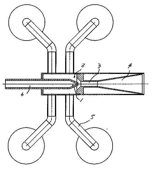
[0007] After analyzing and studying the structure of the existing utility model patent, the sludge, water and gas entering the mixing chamber are mixed and then discharged out of the tank through the diffusion tube. The mixing state of the above water, mud and gas in the diffusion tube is unstable, resulting in When the sludge is discharged more and sometimes less, the sewage discharge effect is not ideal. The present invention adopts the following technical scheme to make the mixing of water, mud and gas more uniform, that is, to add a stable section 3 of equal-diameter holes at the junction of the diffusion pipe and the mixing chamber, so that the water, mud and gas coming out of the mixing chamber After further stable mixing in the diameter hole section, it enters the diffusion section, and the water inlet pipe 6, nozzle 1, mixing chamber 2, diffusion section 4 and mud discharge pipe 5 are not changed. The mixing is more uniform and the sewage discharge effect is improved. ...


PUM


Abstract

The invention discloses a mud discharging device which comprises an inlet pipe, a mixing chamber, a mud discharging pipe and a diffusing pipe, wherein stable pipe sections with equal hole diameters are arranged between a small orifice of the diffusing pipe and an outlet of the mixing chamber. The mud discharging device has the significant advantages of being high in mud discharging efficiency, long in service life and low in cost.

Description

Technical field: [0001] The invention relates to a spraying device, especially a sludge discharger for sludge discharge from an oil tank. Background technique: [0002] The utility model patent of ZL01277219.4 discloses an oil tank sludge discharge device. The sides are respectively connected with the sludge pipe. This kind of sludge discharge device has been used in oil fields for many years, and its overall sludge discharge effect is good, but its sewage discharge effect is still not ideal. In addition, when the concentration of corrosive components contained in oil and gas is high, the sludge discharge The device is severely corroded, and its life is very short, resulting in increased use costs. Invention content: [0003] The object of the present invention is to provide a mud discharger with high mud discharge efficiency, long service life and low cost. [0004] Achieving the purpose and technical solution of the present invention is that a mud discharger includes ...

Claims


Application Information

Patent Timeline
Patent Type & Authority Applications(China)
IPC IPC(8): B08B9/093B08B13/00
CPCB08B9/0933
Inventor 袁志毅张明勇卢祖华
Owner 新乡市乔山机械设备有限公司
Why Eureka
Try Eureka