Wastewater purification apparatus

A technology of sewage purification and sewage treatment device, which is applied in water/sewage treatment, water/sludge/sewage treatment, feeding/discharging device of sedimentation tank, etc. The problems of parts burning and heavy operating box load can achieve the effect of convenient heat dissipation, increase service life, and solve the problem of easy blockage.

Inactive Publication Date: 2018-12-25
杭州棵林科技有限公司
View PDF0 Cites 0 Cited by
  • Summary
  • Abstract
  • Description
  • Claims
  • Application Information

AI Technical Summary

Problems solved by technology

[0004] The purpose of the present invention is to provide a sewage purification device to solve the problem of the sewage purification device in the background technology mentioned above. It is easy to cause burning damage to the parts inside the operation box, causing unnecessary economic losses

Method used


Image

  • Wastewater purification apparatus
  • Wastewater purification apparatus
  • Wastewater purification apparatus

Examples


Embodiment 1

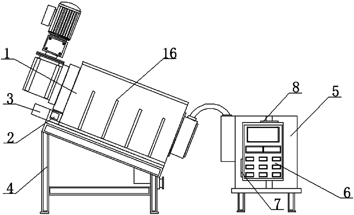
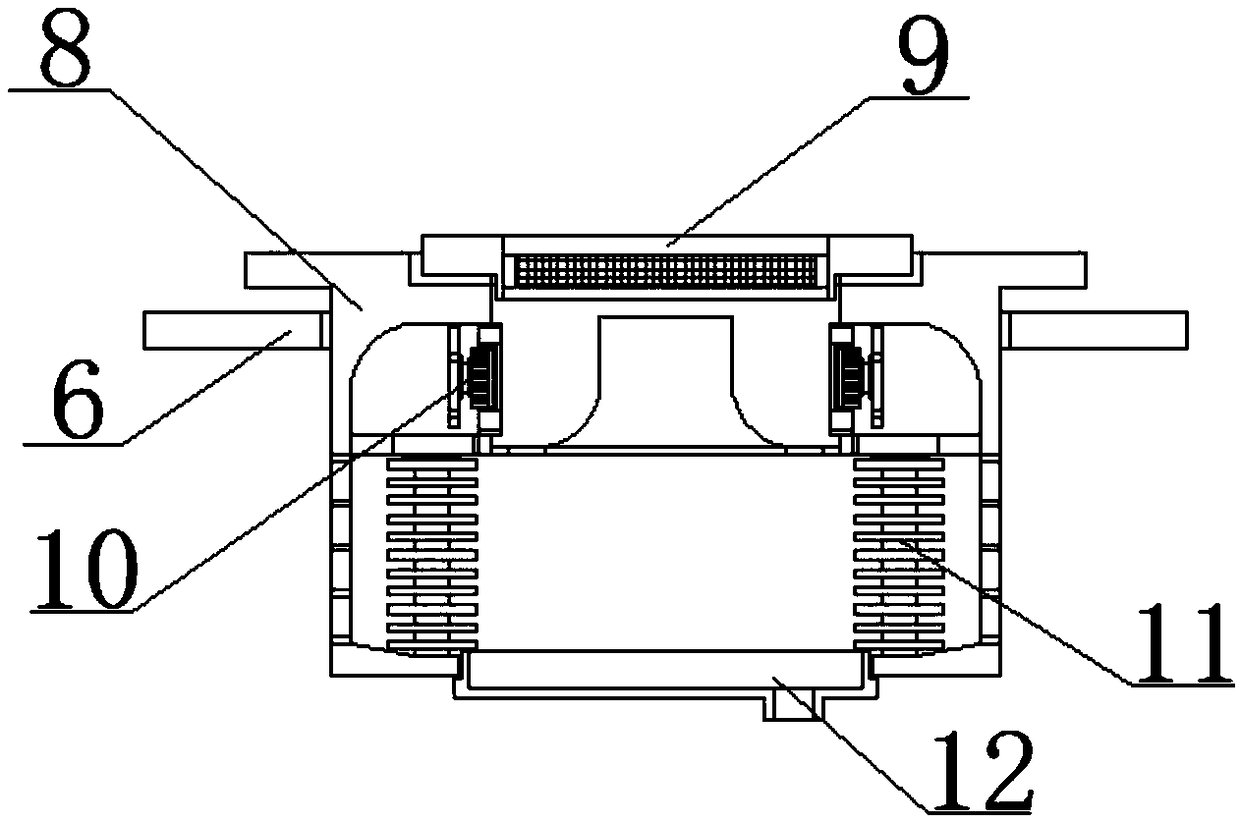
[0020] see figure 1 , figure 2 and image 3 , the present invention provides a technical solution: a sewage purification device, including a sewage treatment device outer shell 16, and also includes a heat dissipation mechanism, one side of the sewage treatment device outer shell 16 is fixed with a screw dehydration box 1, and the screw dehydration box 1 One side is fixed with a mud outlet 2 by bolts, and the other side of the outer shell 16 of the sewage treatment device is fixed with an operation box 6 by bolts. The heat dissipation mechanism includes an air inlet 7, a heat dissipation load-bearing frame 8, a dustproof filter Fan 10, heat absorbing plate 11 and water receiving tray 12, the top of the operation box 6 is fixed with a heat dissipation load-bearing frame 8 by bolts, the bottom of the heat dissipation load bearing frame 8 is fixed with a water receiving tray 12 by screw threads, and the inner side of the heat dissipation load bearing frame 8 A heat-absorbing p...

Embodiment 2

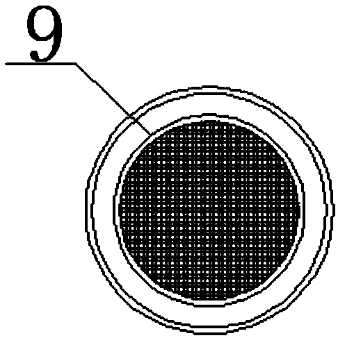
[0024] see Figure 1-Figure 4 , the present invention provides a technical solution: a sewage purification device, including a sewage treatment device outer shell 16, and also includes a heat dissipation mechanism and a cleaning mechanism. One side of the sewage treatment device outer shell 16 is fixed with a screw dehydration box 1 by bolts, and the spiral dehydration One side of the box 1 is fixed with a mud outlet 2 by bolts, and the other side of the outer shell 16 of the sewage treatment device is fixed with an operation box 6 by bolts. The heat dissipation mechanism includes an air inlet 7, a heat dissipation load-bearing frame 8, and a dust filter. 9. Cooling fan 10, heat absorbing plate 11 and water receiving tray 12, the top of the operation box 6 is fixed with a heat dissipation load-bearing frame 8 by bolts, and the bottom of the heat dissipation load-bearing frame 8 is fixed with a water receiving tray 12 by screws, and the heat dissipation load-bearing frame The i...


PUM


Abstract

The invention discloses a wastewater purification apparatus, comprising a wastewater purification apparatus housing, as well as a heat-dissipating mechanism and a cleaning mechanism. One side of the wastewater purification apparatus housing is provided with a spiral dewatering tank in fixed manner; one side of the spiral dewatering tank is provided with a mud discharge bucket in fixed manner; theother side of the wastewater purification apparatus housing is provided with an operating box in fixed manner; the heat-dissipating mechanism includes an air inlet, a heat-dissipating bearer, a dustproof strainer, a cooling fan, a heat-absorbing plate and a water tray; the heat-dissipating bearer is fixed to the top of the operating box. The cooling fan mounted at the top of the operating box andthe air inlet mounted in one side of the operating box help circulate air in the operating box; the dustproof strainer mounted at the top of the heat-dissipating bearer helps prevent dust for the heat-dissipating bearer; the water tray mounted at the bottom of the heat-dissipating bearer helps collect vapor on the heat-absorbing plate; the problem that the operating box has poor heat-dissipating performance is solved.

Description

technical field [0001] The invention belongs to the technical field of sewage purification, and in particular relates to a sewage purification device. Background technique [0002] Sludge is an inevitable product of sewage treatment in sewage treatment plants and sewage stations. Untreated sludge entering the environment will directly bring secondary pollution to water bodies and the atmosphere, and it will also affect the ecological environment and human activities. would pose a serious threat. [0003] When the existing sewage purification device is in use, the load on the operation box is relatively large, and a large amount of heat is easily generated inside the operation box. However, the heat dissipation performance of the general operation box is poor, which easily leads to the burning of parts inside the operation box, resulting in unnecessary The problem of economic loss, for this we propose a sewage purification device. Contents of the invention [0004] The pu...

Claims


Application Information

Patent Timeline
Patent Type & Authority Applications(China)
IPC IPC(8): C02F1/00C02F11/12B01D21/24B01D21/26B01D35/14
CPCC02F1/008B01D21/245B01D21/262B01D35/14C02F11/12
Inventor 应昌浩
Owner 杭州棵林科技有限公司
Why Eureka
Try Eureka