Hard-tooth-surface shaft-mounted speed reducer

A shaft-mounted, reducer technology, applied in the direction of gear transmission, mechanical equipment, transmission, etc., can solve the problems of high production cost, increase the length of the reducer, large ineffective space, etc. The effect of deceleration performance and sealing performance improvement

Active Publication Date: 2014-08-20
JIANGSU JINCHANGCHENG SPEED REDUCER
View PDF7 Cites 0 Cited by
  • Summary
  • Abstract
  • Description
  • Claims
  • Application Information

AI Technical Summary

Problems solved by technology

[0002] The traditional structure of the reducer adopts the upper and lower box structures, and the lower box supports the input, intermediate, and output shafts in sequence. The upper and lower box structures are different, and the supporting bearings of each shaft are different, which cannot be used universally, and the production cost is high; In addition, each The shafts are arranged in sequence, which increases the length of the reducer, the box is bulky, and the invalid space in the box is large, which increases the production cost and is not convenient for transportation and installation.

Method used


Image

  • Hard-tooth-surface shaft-mounted speed reducer

Examples


Embodiment Construction

[0015] The present invention will be further described below in conjunction with drawings and embodiments.

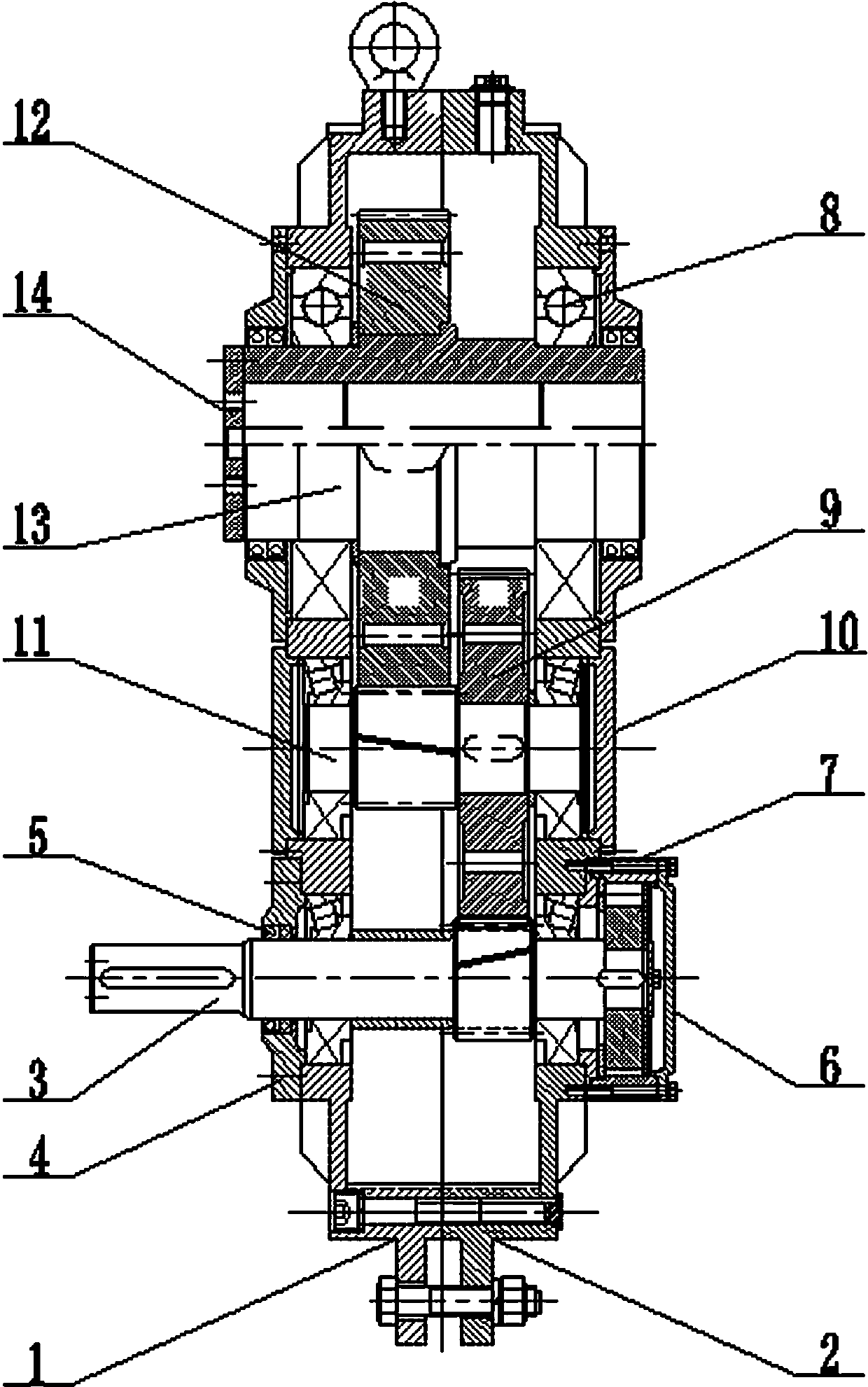
[0016] figure 1 As shown, a hard tooth surface shaft-mounted reducer includes a left box body 1, a right box body 2, an input gear shaft 3, an input transparent cover 4, a double oil seal 5, an input stuffy cover 6, a roller backstop 7, Bearing 8, pinion 9, middle stuffy cover 10, middle gear shaft 11, bull gear 12, output hollow shaft 13 and output transparent cover 14. The left box 1 and the right box 2 are the same, the left and right boxes 1 and 2 are connected by bolts, the input gear shaft 3 and the intermediate gear shaft 11 are symmetrically installed in the lower parts of the left and right boxes 1 and 2 respectively, and the output is hollow The shaft 13 is installed on the upper part of the left and right boxes 1 and 2, parallel to the input gear shaft 3 and the intermediate gear shaft 11, forming a triangular space structure; one end of the input gear shaft...


PUM


Abstract

The invention relates to a hard-tooth-surface shaft-mounted speed reducer. The hard-tooth-surface shaft-mounted speed reducer comprises a left box, a right box, an input gear shaft, an intermediate gear shaft and an output shaft. One end of the input gear shaft is connected to an input piercing cover in a penetrating and sealing mode through double oil seals, and the other end of the input gear shaft is connected to the interior of an input gland through a roller brake. The two ends of the output shaft are connected to a left output through cover and a right output through cover in a penetrating and sealing mode through double oil seals. By the adoption of the left box and the right box which are the same or are symmetrical, machining and general interchange of the boxes are facilitated. The shafts are supported by bearings which are the same, so that general interchange and consistency of supporting stability are facilitated, and improvement on decelerability is facilitated.

Description

technical field [0001] The invention relates to a reducer, in particular to a hardened shaft-mounted reducer. Background technique [0002] The traditional structure of the reducer adopts the upper and lower box structures, and the lower box supports the input, intermediate, and output shafts in sequence. The upper and lower box structures are different, and the supporting bearings of each shaft are different, which cannot be used universally, and the production cost is high; In addition, each The shafts are arranged in sequence, which increases the length of the reducer, the box body is bulky, and the invalid space in the box is large, which increases the production cost and is not convenient for transportation and installation. Contents of the invention [0003] In view of the above disadvantages, the present invention provides a shaft-mounted gear reducer with hard tooth surfaces, which is simple in structure, compact in the box, highly versatile in components, low in p...

Claims


Application Information

Patent Timeline
Patent Type & Authority Applications(China)
IPC IPC(8): F16H1/22F16H57/023F16H57/029F16H57/02
CPCF16H1/22F16H57/023F16H57/029F16H57/033F16H2057/02086F16H2057/0335
Inventor 尤志锋蔡建新
Owner JIANGSU JINCHANGCHENG SPEED REDUCER
Why Eureka
Try Eureka