Shifting register unit, grid drive circuit, display device and drive method

A gate drive circuit and shift register technology, applied in the field of gate drive circuits and shift register units, can solve problems such as enhanced shutdown

Active Publication Date: 2014-08-20
BOE TECH GRP CO LTD +1
View PDF5 Cites 97 Cited by
  • Summary
  • Abstract
  • Description
  • Claims
  • Application Information

AI Technical Summary

Problems solved by technology

[0005] Aiming at the deficiencies of the prior art, the present invention provides a shift register unit, a gate drive circuit, a display device and a driving method, which enhances the turn-off effect of the switching element that will cause leakage through the additional turn-off enhancement unit, Greatly reduce the leakage of PU points, thus solving the problem of dark lines caused by touch scanning

Method used


Image

  • Shifting register unit, grid drive circuit, display device and drive method
  • Shifting register unit, grid drive circuit, display device and drive method
  • Shifting register unit, grid drive circuit, display device and drive method

Examples


Embodiment 1

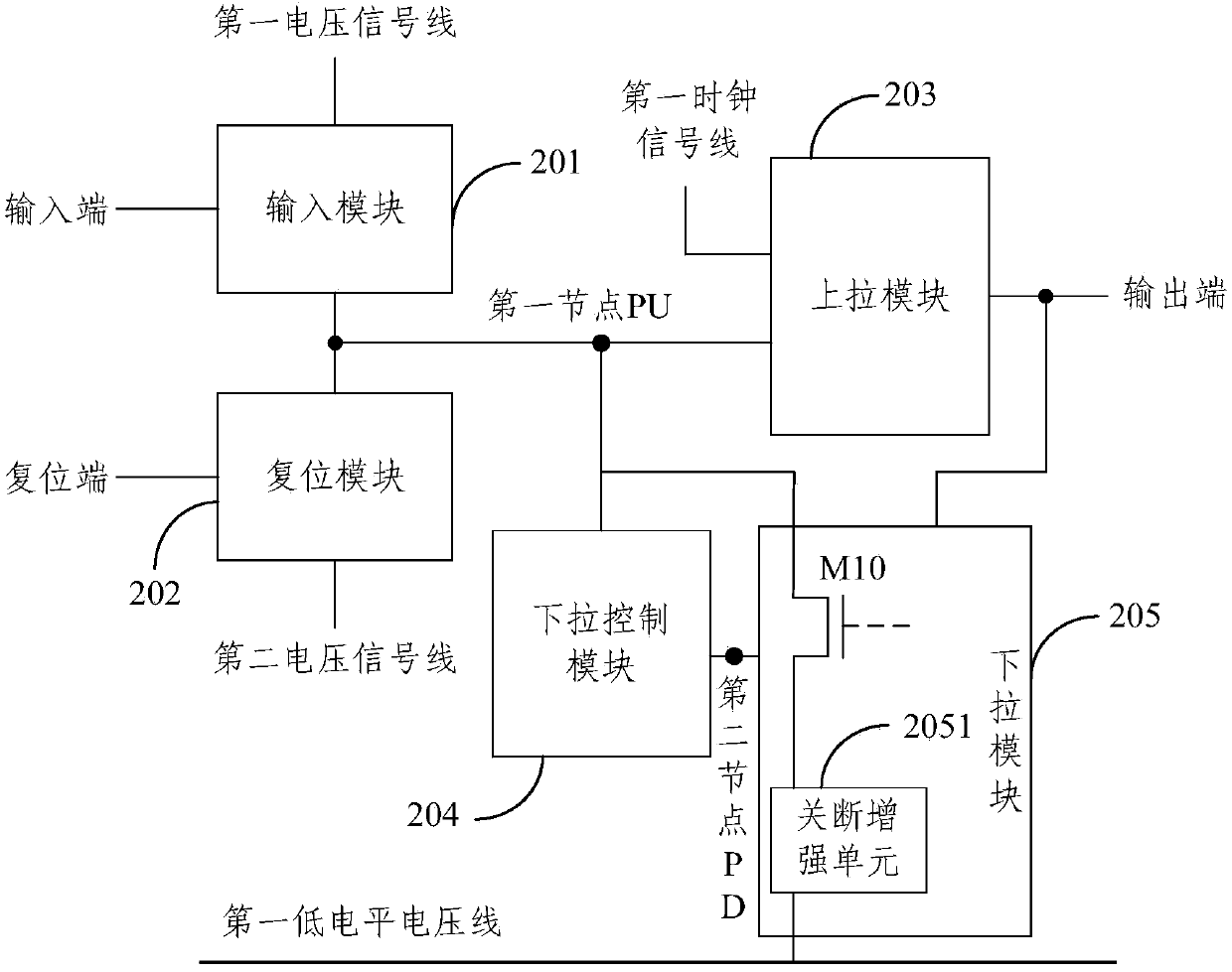
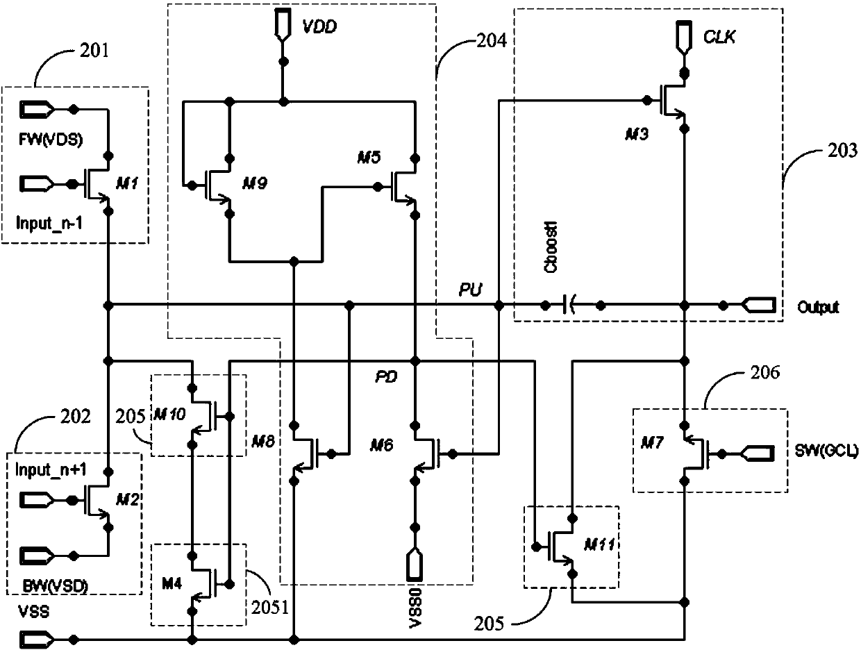
[0042] An embodiment of the present invention proposes a shift register unit, wherein the shift register unit includes:

[0043] The input module 201 is configured to conduct the connection between the first node PU and the first voltage signal line under the control of the signal connected to the input terminal, and the first node PU is the connection point between the input module and the pull-up module;

[0044] A reset module 202, configured to conduct the connection between the first node PU and the second voltage signal line under the control of the signal connected to the reset terminal;

[0045] A pull-up module 203, located between the first node PU and the output terminal, configured to conduct the connection between the first clock signal line and the output terminal under the control of the voltage PU at the first node;

[0046] The pull-down control module 204 is configured to control the potential of the PD at the second node according to the potential at the fir...

Embodiment 2

[0074] Based on the same inventive concept, an embodiment of the present invention proposes a gate drive circuit, including a plurality of cascaded shift register units, wherein the shift register unit adopts any A shift register unit.

[0075] Since the display device provided in the embodiment of the present invention has the same technical features as any shift register unit provided in Embodiment 1, it can also solve the same technical problem and produce the same technical effect.

Embodiment 3

[0077] Based on the same inventive concept, an embodiment of the present invention proposes a display device, which includes a gate drive circuit, and is characterized in that the display device uses any gate drive circuit as described in Embodiment 2 as its gate Pole drive circuit, the display device can be: liquid crystal panel, electronic paper, OLED panel, mobile phone, tablet computer, TV, monitor, notebook computer, digital photo frame, navigator and any other product or component with display function.

[0078] Since the display device provided in the embodiment of the present invention has the same technical features as any gate driving circuit provided in Embodiment 2, it can also solve the same technical problem and produce the same technical effect.


PUM


Abstract

The invention provides a shifting register unit, a grid drive circuit, a display device and a drive method. The shifting register unit comprises an input module, a reset module, an upward pull module, a downward pull control module and a downward pull module. The downward pull module comprises a tenth switch element used for enabling a first node and a first low level voltage wire to be controlled to be switched on, and a switch-off boost unit. The switch-off boost unit is used for stopping one end of the tenth switch element from being connected with the first low level voltage wire when the tenth switch element is in an off state. According to the shifting register unit, the grid drive circuit, the display device and the drive method, through the additionally-arranged switch-off boost unit, the switch-off function of the switch element in which electric leakage can happen is enhanced, PU point electric leakage is greatly reduced, and therefore the problem that touch scanning can cause concealed wiring display is solved.

Description

technical field [0001] The invention relates to the field of touch screen display, in particular to a shift register unit, a gate drive circuit, a display device and a drive method. Background technique [0002] At present, the touch screen display panel has become the mainstream mobile display terminal configuration, among which the capacitive touch screen CTP (Capacity Touch Panel) has absolute advantages in many aspects. In order to reduce the thickness of the box, the capacitive touch screen often adopts the method of integrating the In Cell (embedded) touch panel and the LCD panel, including Full In Cell (integrated embedded) and Hybrid In Cell (hybrid embedded). These two methods both involve the problem of time-sharing driving of signals in the touch scanning phase and display driving signals. [0003] Taking Hybrid In Cell as an example, the method of time-sharing driving is to use the alternate scanning method of "display phase-touch scanning phase-display phase-to...

Claims


Application Information

Patent Timeline
Patent Type & Authority Applications(China)
IPC IPC(8): G09G3/20G11C19/28G06F3/044
CPCG09G3/3677G09G2310/0286G09G2320/0233G11C19/28G06F3/041661G06F3/04184G06F3/0412G09G3/3696G09G2300/0809G09G2310/0202
Inventor 龙跃黄炜贇王杨
Owner BOE TECH GRP CO LTD
Why Eureka
Try Eureka