commutator motor

A commutator and motor technology, used in DC commutators, current collectors, rotary current collectors, etc., can solve the problems of reduced stability, service life, large tolerances, etc., and achieve stable guidance, low cost, and reliable support. Effect

Active Publication Date: 2016-10-26
ROBERT BOSCH GMBH
View PDF6 Cites 0 Cited by
  • Summary
  • Abstract
  • Description
  • Claims
  • Application Information

AI Technical Summary

Problems solved by technology

[0003] It is disadvantageous in the prior art that the brush holder is designed as a rectangular carbon cartridge with relatively large tolerances of the associated motor brush coverage from the carbon brush to the current collector, In this case, a precise and stable guidance of the carbon brushes is only possible under limited conditions, so that the current wave signal generated by the commutation has only a limited stability
The defined robustness is further reduced over the service life of the carbon brushes, so that the current wave signals generated during commutator motor operation can only be used to precisely determine the rotational position of the rotor in limited cases.

Method used


Image

  • commutator motor
  • commutator motor
  • commutator motor

Examples


Embodiment Construction

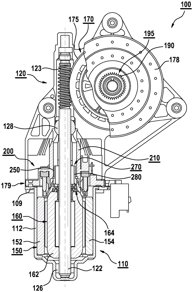
[0029] figure 1 An exemplary drive device 100 is shown, which as shown has a drive motor 110 and a switching mechanism 120 coupled to the drive motor. The drive device 100 is preferably used as a drive device for electric window regulators in a motor vehicle. However, it should be pointed out that the drive device 100 is not restricted to use for a window regulator, but can be used for a plurality of different actuating drives. For example, the device 100 can alternatively be used in an actuating drive for a seat adjuster.

[0030] The drive motor 100 can be controlled or adjusted in such a way that both reversible operation and presetting are possible with respect to the desired rotational speed. By way of example, the drive motor 110 is equipped with a motor housing 112 which has a fastening flange 109 . Switching mechanism 120 is for example equipped with a gear housing 178 which has a fastening section 179 . The fastening flange 109 of the motor housing 108 is fastened...


PUM


Abstract

In the case of a commutator motor with a commutator (270), which has a collector (280) which, at a collector contact surface (289), is in sliding contact with associated brushes (250, 290), wherein at least one brush (250) is arranged in an associated brushholder (220), the brushholder (220) has at least one guide web (231, 237), which is aligned in the radial direction of the collector (280) and engages in at least one guide groove (252, 254) provided in the at least one brush (250).

Description

technical field [0001] The invention relates to a commutator motor with a commutator having a current collector on a current collector running surface in sliding contact with an associated brush, wherein at least one brush is arranged on the associated brush in the bracket. Background technique [0002] Commutator motors are known from the prior art which have a commutator designed for commutation. The commutator has current collectors located on a current collector running surface in sliding contact with associated brushes, which are arranged on the rotor of the commutator motor. The motor current necessary for operation is supplied to the commutator motor via brushes, for example carbon brushes, arranged relative to each other at a predetermined brush angle in an associated brush holder, and via a current collector. During commutation of such a commutator motor, so-called “current waves” are generated which can be used to determine the corresponding rotational position...

Claims


Application Information

Patent Timeline
Patent Type & Authority Patents(China)
IPC IPC(8): H01R39/41
CPCH01R39/41H01R39/38H02K5/148H02K7/1166H02K13/10H02K23/18
Inventor L-D.安丁
Owner ROBERT BOSCH GMBH
Why Eureka
Try Eureka