
Control system for synchronous capacitor switch

A technology for control systems and capacitors, applied in electrical components, circuit devices, battery load switching, etc., to solve problems such as expensive, difficult to put into use/installation, and complicated controllers

Active Publication Date: 2014-08-20
HUBBELL INC
View PDF8 Cites 1 Cited by
  • Summary
  • Abstract
  • Description
  • Claims
  • Application Information

AI Technical Summary

Problems solved by technology

These systems may be acceptable for some applications, but fail to perform in an acceptable manner for more sensitive applications
[0004] Controllers configured to close when the voltage across the capacitor switch approaches zero volts are typically complex, expensive, and difficult to implement / install because they must handle a complex mix of mechanical and electrical variations

Method used


Image

  • Control system for synchronous capacitor switch
  • Control system for synchronous capacitor switch
  • Control system for synchronous capacitor switch

Examples


Embodiment Construction

[0020] Before referring to the figures, it should be noted that references to "front", "rear", "rear", "upward", "downward", "inner", "outer", "right", "left" and / or or other directional terms in this description are used only to identify various elements as they are oriented in the figures. These terms are not intended to limit the elements they describe, as various elements may be oriented differently in various applications.

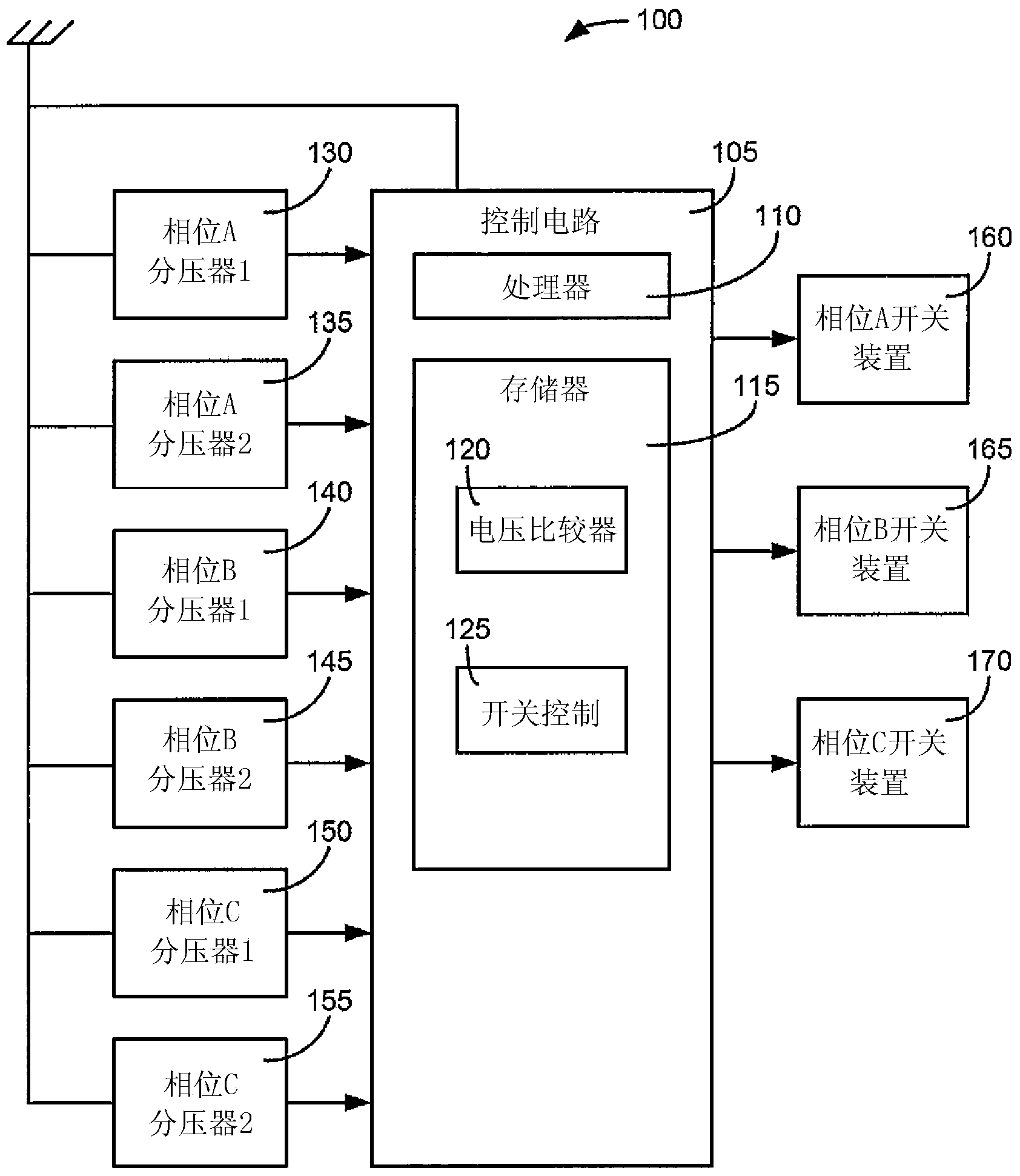
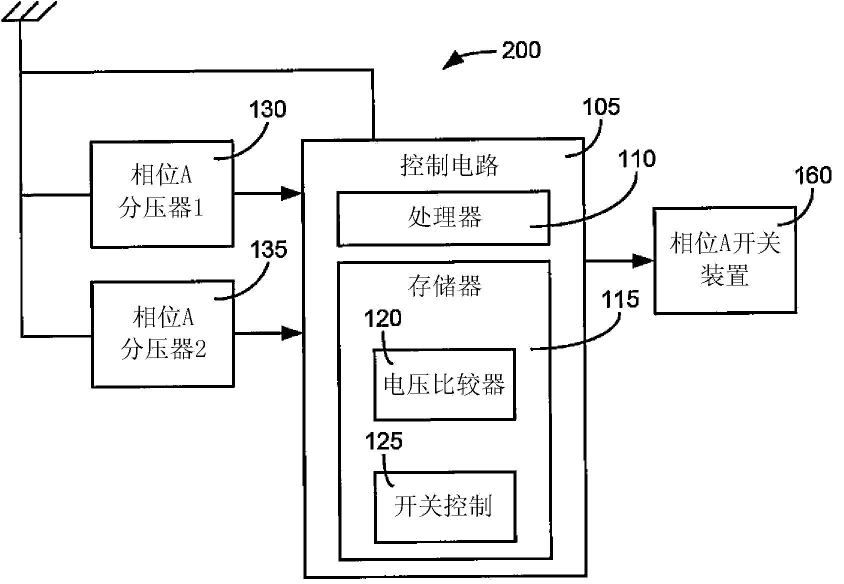
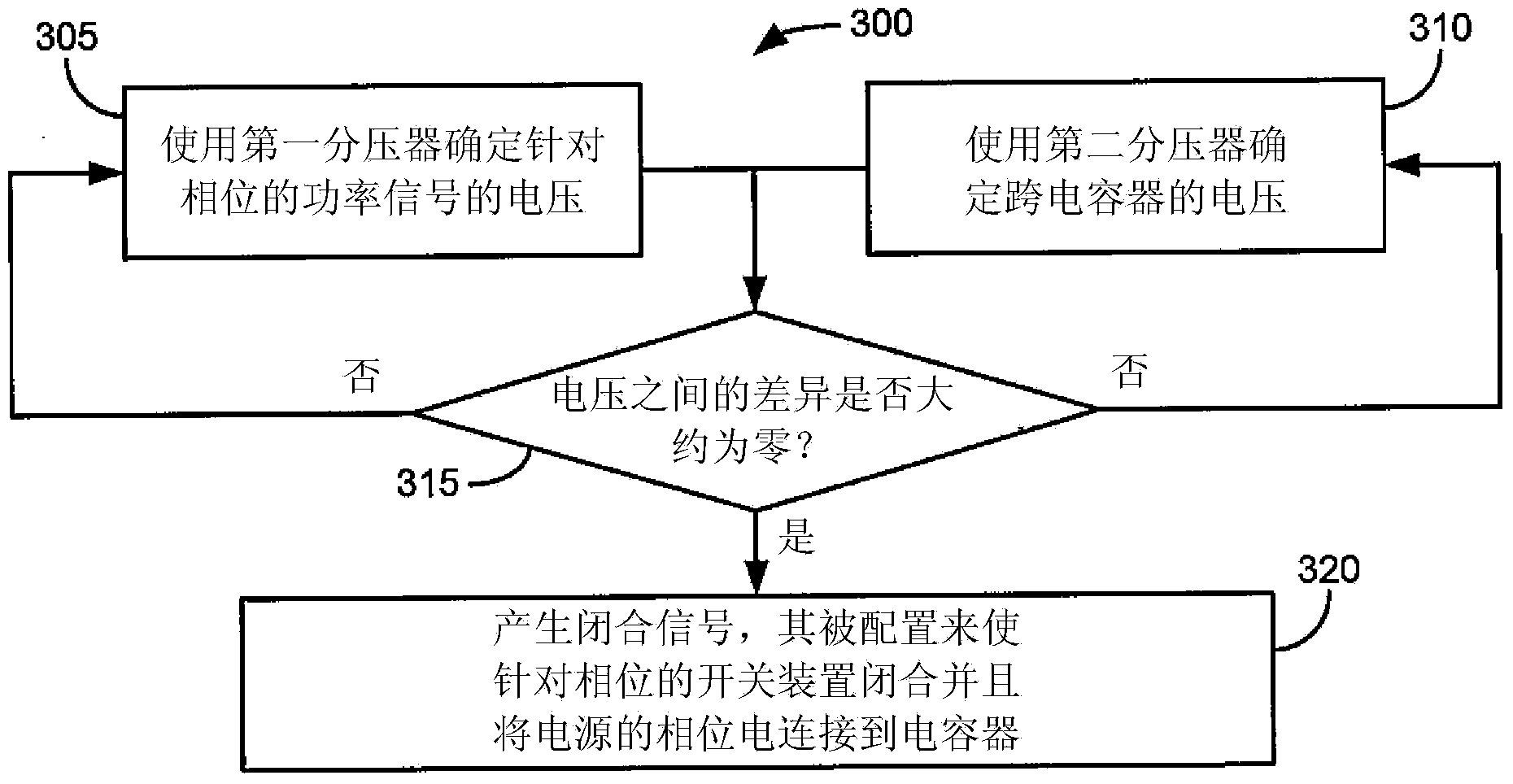
[0021] Referring generally to the figures, systems and methods for controlling a connection between a power source (eg, a multi-phase (eg, three-phase) power source) and one or more capacitors are provided in accordance with various exemplary embodiments. The switching system may consist of separate switching devices or contactors for each phase of a polyphase system (eg, three contactors for three phases). In various embodiments, separate voltage dividers may be provided on each side of the switching device for each phase (eg, one on the capacitor o...


PUM


Abstract

Systems and methods for connecting a power source to switched capacitors are provided. A method may be used in controlling the connection of a multiple phase power source to a plurality of capacitors. Each phase of the multiple phase power source is electrically connectable to at least one of the capacitors through a switching device. The method comprises, for each phase of the multiple phase power source, determining a first voltage of a power signal for the respective phase of the power source using a first voltage divider that is electrically connected to a first terminal of the switching device for the phase. The method further comprises determining a second voltage across a capacitor that is connected to a second terminal of the switching device for the phase. The second voltage is determined using a second voltage divider that is connected to the second terminal of the switching device.

Description

Background technique [0001] The present invention relates generally to the field of electrical switching control systems. More specifically, the present invention relates to systems and methods for controlling switches to selectively connect a power source (eg, three-phase, medium voltage power source) to one or more capacitors. [0002] Switched capacitor banks are installed on poles and in substations to apply power factor correction to the grid in response to the application and removal of heavy industrial inductive loads (eg, electric motors) (eg, by changing load phasing). When the load is out of phase, the extra reactive current increases transmission losses, which leads to wasted energy and the need for additional generating capacity. In some systems, a separate control senses the voltage-to-current correlation and commands the capacitor switches to open and close based on that relationship. Applying capacitors can help improve the transfer efficiency of electrical en...

Claims


Application Information

Patent Timeline
Patent Type & Authority Applications(China)
IPC IPC(8): H02J3/00
CPCH02J3/1821H02J3/18Y02E40/30H02J7/0068H02J7/345
Inventor 约瑟夫·P·格罗瓦茨罗伯特·A·特拉斯卡
Owner HUBBELL INC
Learn More