Reel product slitting machine tool holder

A technology of slitting knife and slitting machine, which is applied in metal processing and other directions, can solve the problems of difficult surface hardness treatment of parts and high manufacturing cost

Inactive Publication Date: 2014-08-27
YUNNAN TONGPRINT
View PDF7 Cites 5 Cited by
  • Summary
  • Abstract
  • Description
  • Claims
  • Application Information

AI Technical Summary

Problems solved by technology

[0003] In order to solve the problems in the prior art that the slitting knife seat is designed as a circular ring, the surface hardness of parts is difficult to deal with and the manufacturing cost is high, the present invention provides a reel product slitting machine knife seat, the knife The seat is installed on the frame at the front end of the winding disc of the winding unit of the printing production line. A slitting knife roller is installed on the frame. A circular slitting knife is installed on the slitting knife roller. A backing roller is installed under the knife roller, and a circular slitting knife holder is installed on the backing roller. The outer peripheral edge of the slitting knife holder is closely attached to the outer peripheral edge of the slitting knife. A protruding inner ring is processed on one side of the slitting knife seat, and an annular blade is set on the inner ring. On the inner ring of the machine, a card slot is processed, and a snap ring is installed in the card slot

Method used


Image

  • Reel product slitting machine tool holder
  • Reel product slitting machine tool holder

Examples


Embodiment 1

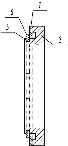
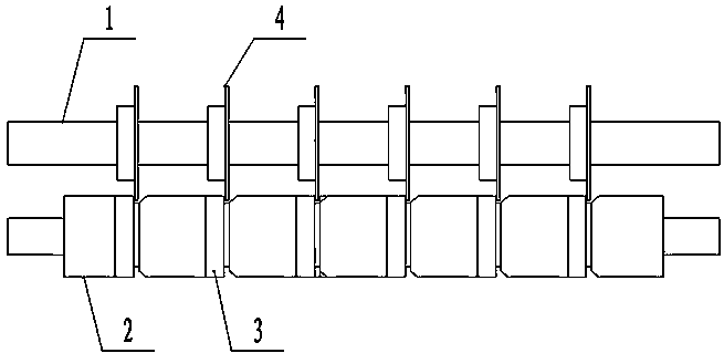
[0007] Embodiment one: if figure 1 As shown, a reel product slitting machine knife seat is installed with a slitting knife roller 1 on the frame at the front end of the winding unit of the printing production line, and a circular ring is installed on the slitting knife roller 1. The slitting knife 4 is equipped with a backing roller 2 below the slitting knife roller 1, and an annular slitting knife holder 3 is installed on the backing roller 2, and the outer peripheral edge of the slitting knife holder 3 and the slitting The outer circumference edge of knife 4 is close together, on one side of the ring-shaped slitting knife seat 3, a protruding inner ring 5 is processed, and a piece of annular blade 7 is set on the inner ring 5, Annular blade 7 is identical with the outer circumference diameter of slitting knife holder 3, on the inner ring 5 that is close to annular blade 7 outsides, is processed with draw-in groove, and snap ring 6 is installed in draw-in groove.


PUM


Abstract

A reel product slitting machine tool holder which is in an inner circular ring shape sleeves on a pad roller which is arranged under a slitting tool of a winding unit; a protruding inner circular ring is machined in one lateral side of the tool holder; an annular blade sleeves the inner circular ring; a clamping groove is machined in the inner circular ring which is closely adhered to the outer side of the annular blade; a clamping ring is installed inside the clamping groove. According to the technical scheme, when the annular blade is abraded, only the annular blade is replaced, the integral slitting tool holder is not required to be replaced, and accordingly the maintenance and replacement costs of the annular blade are greatly reduced and the annular blade can be produced by high rigidity materials, the machining difficulty is low and the manufacturing costs are small compared with that rigidity processing is performed in the lateral side of the integral slitting tool holder, the blade can be turned over by one surface for continuous utilization when one side of the annular blade is abraded, and the service life of the annular blade is greatly increased.

Description

technical field [0001] The invention belongs to the technical field of gravure printing equipment, and relates to a cutter seat of a slitting machine for reel products. Background technique [0002] The standard roll paper used in the printing production line has a large width. In the printing process of many products, the same pattern is printed side by side on the roll paper. Slitting with the backing roller, and winding into multiple narrow reels after slitting. At present, in the prior art, a slitting knife seat is installed on the backing roller, which is designed as a whole ring, and an annular knife groove is processed on the backing roller on one side of the ring, and the slitting knife roller The edge of the slitting knife is close to the edge of the slitting knife seat, and the outer circumference of the slitting knife is inserted into the annular knife groove. For the slitting knife holder with this structure, when the outer edge of the side in contact with the ...

Claims


Application Information

Patent Timeline
Patent Type & Authority Applications(China)
IPC IPC(8): B26D7/26B26D1/143
Inventor 赛顺元郝永金钱江
Owner YUNNAN TONGPRINT
Why Eureka
Try Eureka