Counter slot structure for artificial counters

A counter and artificial technology, applied in the direction of building structure, construction, safety transaction partitions, etc., can solve the problems of power consumption, waste of time, laborious to pick up, etc., to avoid time waste, improve operating efficiency, and facilitate pick-up operations Effect

Active Publication Date: 2016-06-08
浙江富海建筑装饰工程股份有限公司
View PDF10 Cites 0 Cited by
  • Summary
  • Abstract
  • Description
  • Claims
  • Application Information

AI Technical Summary

Problems solved by technology

[0002] At the manual transaction counters of banks or stations, transactions are carried out through counter slots. Customers pass in ID cards, transaction slips, RMB, etc. through the counter slot outside the counter, and staff hand out tickets, vouchers, RMB, etc. inside the counter. However, the currently used counter slots have a relatively deep slot diameter and a large bottom area, so it is difficult to take out the tickets, vouchers, RMB, etc. inside, especially small things such as coins, which are very laborious; these places are often crowded. There is a lot of traffic, and there is often a long queue, which is a waste of time
The Chinese patent of the patent number CN103184824 disclosed a bank automatic counter slot on July 3, 2013. The slot shape is a cube, and the slot plate is provided with a slot plate. On the conveyor belt, the conveyor belt is driven by a motor, and the switch button of the motor is set on the desktop of the bank staff, which can automatically transfer the cash and various bank certificates placed in the slot to the bank staff and customers conveniently, but this The installation of the counter tank is troublesome, which not only increases the workload of the staff, but also consumes electric energy, which is not energy-saving

Method used


Image

  • Counter slot structure for artificial counters
  • Counter slot structure for artificial counters
  • Counter slot structure for artificial counters

Examples


Embodiment Construction

[0016] The present invention will be further described below in conjunction with the accompanying drawings and specific embodiments.

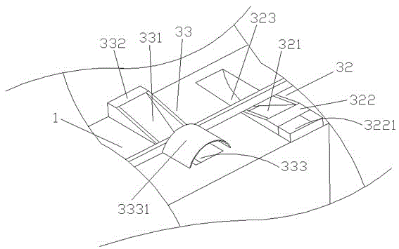
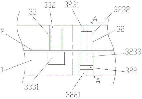
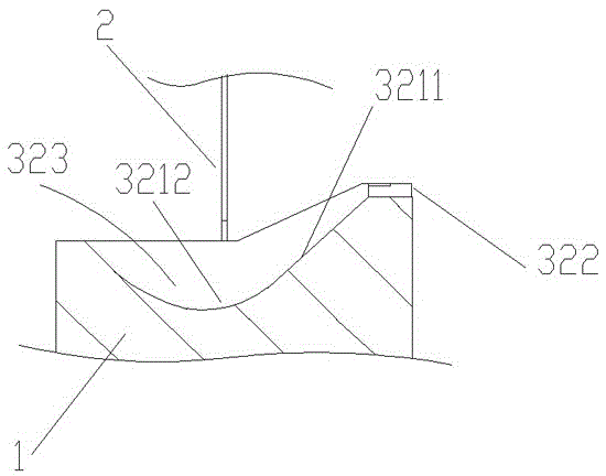
[0017] as attached figure 1 , 2 . The counter groove structure of the artificial counter shown in 3 includes a wall 1, a protective glass 2 vertically arranged on the top of the wall 1, and an installation groove arranged on the wall 1 and directly below the protective glass 2. A channel groove is installed, and the channel groove includes a first channel groove 32 and a second channel groove 33 that span the inside and outside of the protective glass and are 10-30cm apart from each other, and the interval of this embodiment is 15cm; the first channel groove 32 includes points from outside the counter , and the first inclined passage 321 that is arranged downwards, the first end 322 that is arranged on the counter outer end of the first inclined passage 321, and the inner groove 323 that is arranged on the counter inner end of the first inclin...


PUM


Abstract

The invention relates to a counter groove structure of an artificial counter, which comprises a wall, a protective glass arranged on the wall, and a passage groove, and the passage groove includes first and second passage grooves separated from each other; the first passage The slot includes a first inclined channel pointing from the outside of the counter to the inside of the counter and inclined downwards, a first end arranged on the outer side of the counter of the first inclined channel, and a first end arranged on the inner side of the counter of the first inclined channel. The inner groove at the end; the first channel groove includes a second inclined channel directed upward from the outside of the counter to the inside of the counter, and a second end arranged at the inner end of the counter of the second inclined channel; an outer groove at the counter-outboard end of the second inclined channel. The invention is simple in structure, convenient for pick-up operation, avoids conflicts between pick-up and delivery through different channel slots, can avoid time waste caused by pick-up, and improves the operation efficiency of the counter.

Description

technical field [0001] The invention relates to a counter transaction device, in particular to a counter groove structure of a manual counter. Background technique [0002] At the manual transaction counters of banks or stations, transactions are carried out through counter slots. Customers pass in ID cards, transaction slips, RMB, etc. through the counter slot outside the counter, and staff hand out tickets, vouchers, RMB, etc. inside the counter. However, the currently used counter slots have a relatively deep slot diameter and a large bottom area, so it is difficult to take out the tickets, vouchers, RMB, etc. inside, especially for relatively small things such as coins; There is a lot of traffic, and there are often long queues, which is a waste of time. The Chinese patent with the patent number CN103184824 disclosed a bank automatic counter slot on July 3, 2013. The slot shape is a cube, and a slot plate is arranged in the slot. On the conveyor belt, the conveyor belt...

Claims


Application Information

Patent Timeline
Patent Type & Authority Patents(China)
IPC IPC(8): E05G7/00
Inventor 沈敏英沈越峰费浩亮王霞萍潘锦乐顾晓栋周文胜张波夏俊景沈伟强赵敏闵宇炜边秋园陈玮
Owner 浙江富海建筑装饰工程股份有限公司
Why Eureka
Try Eureka